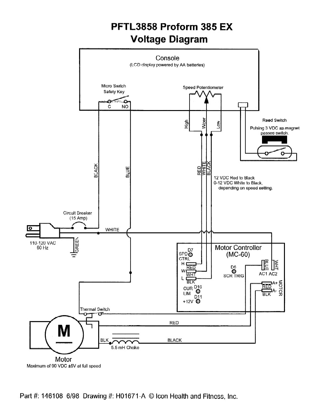
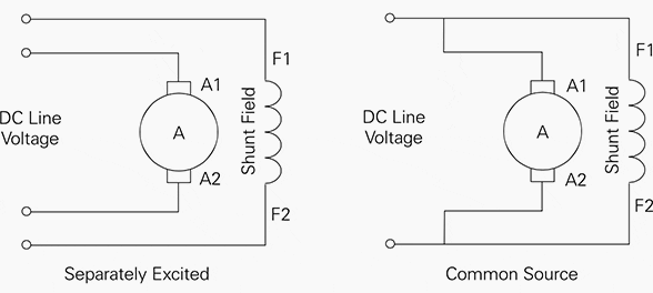
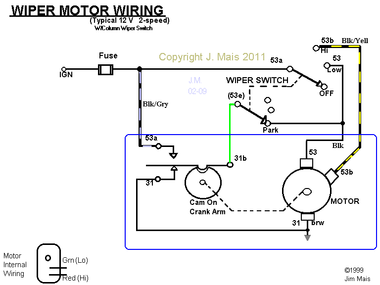
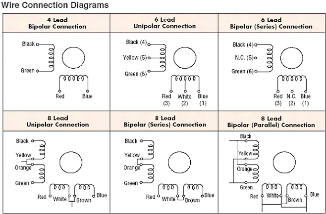
Use figure 1 if your motor has a single voltage shunt field. For a visual picture of typical wiring configurations reference the following guide.
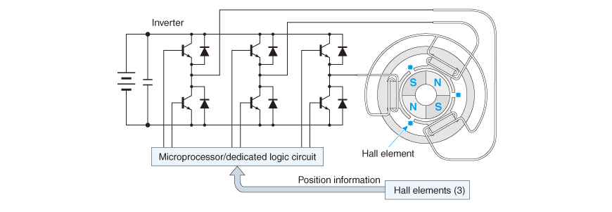
1 3 2 Brushless Dc Motor Nidec Corporation
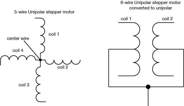
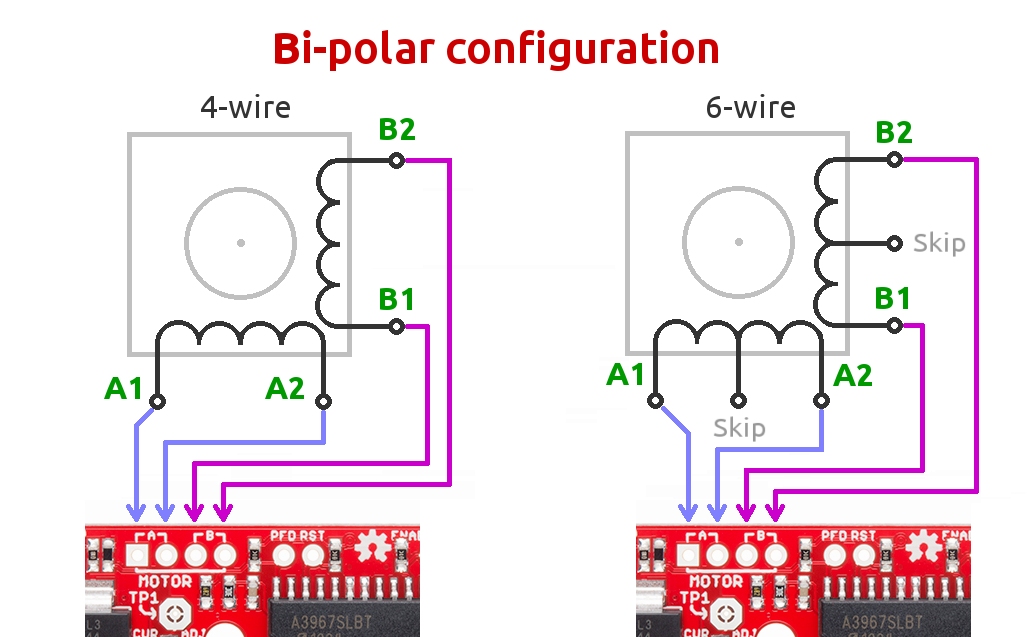
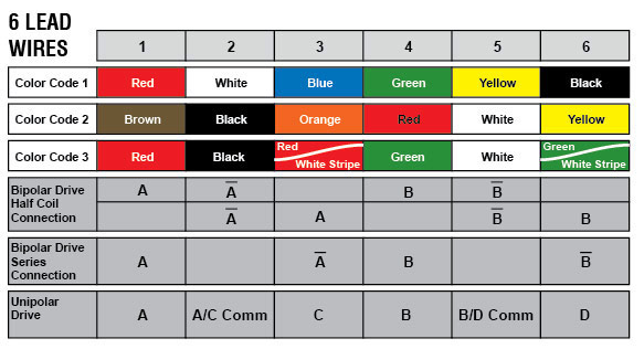
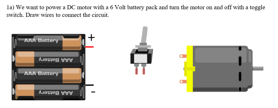
Dc motor wiring diagram 6 wire. A double pole double throw switch is used for this purpose but you have to wire it up correctly. Motor wiring diagram dc. Here is the video where i used a motor to build a power snowblower chute rotator. As 183 wiring diagram with switch. These connections are in accordance with nema mg 1 and american standards publication 06. The extra two wires in a 6 wire bipolar stepper allow you to use it as a 4 coil motor instead of a 2 coil by using the center wire on each coil as a common supply or ground.
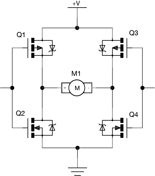
Ac80 ac90 ac100 single phase motors. Inst maint wiringqxd 5032008 1002 am page 6. When you need to control a dc motor such as a dc linear actuator you usually need to be able to swap the polarity on the wires going to the motor. Some condenser fan motors wire to a circuit board while others use proprietary plugs for their connectors. A 3 position 6 terminal toggle switch can be used in many other applications and in many other wiring variations. Ac80 ac90 ac100 single phase motors.
6 wire motors have three wires per phase. These diagrams are current at the time of publication check the wiring diagram supplied with the motor. Hvac condenser fan motor wiring diagram. In addition you can turn a 6 wire bipolar into a 5 wire unipolar by joining the two center wires as shown in figure 11. Wiring a dc motor and universal motor for speed control. In this video i explain and demonstrate how to wire a double pole double throw switch dpdt to a 12v electric motor.
Wire a dpdt rocker switch for reversing polarity. Use figure 2 if your motor has a dual voltage shunt field. Here well cover how to use a 3 position 6 blade toggle to run a 12volt dc motor or 12volt actuator in forward and reverse directions. Refer to the motor manufacturers data on the motor for wiring diagrams on standard frame ex e ex d etc. Motor connections your motor will be internally connected according to one of the diagrams shown below. I use a vacuum motor electric lawn mower and treadmill motors to demonstration some cheap options for speed control and wiring to the wall.
Two wire leads connect to either end of one phase with a third wire connected to the center point between the coils as shown in figure 1. 4 wire reversible psc motor. This third wire is commonly referred to as the phases center tap. Finally this guide is intended to be used as a general overview of common condenser unit wiring schematics. To connect the motor for unipolar operation the six wires are configured essentially as an h bridge.
