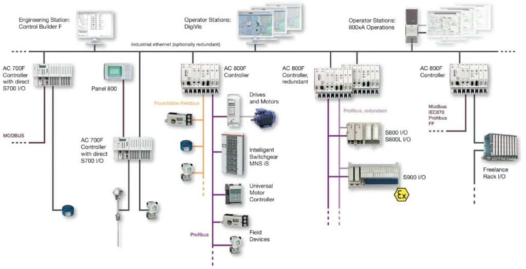
It differs from the centralized control system wherein a single controller at central location handles the control function but in dcs each process element or machine. 12p15mmsq analog inpu electrical househome wiring electricalhome wiringelectrical house.
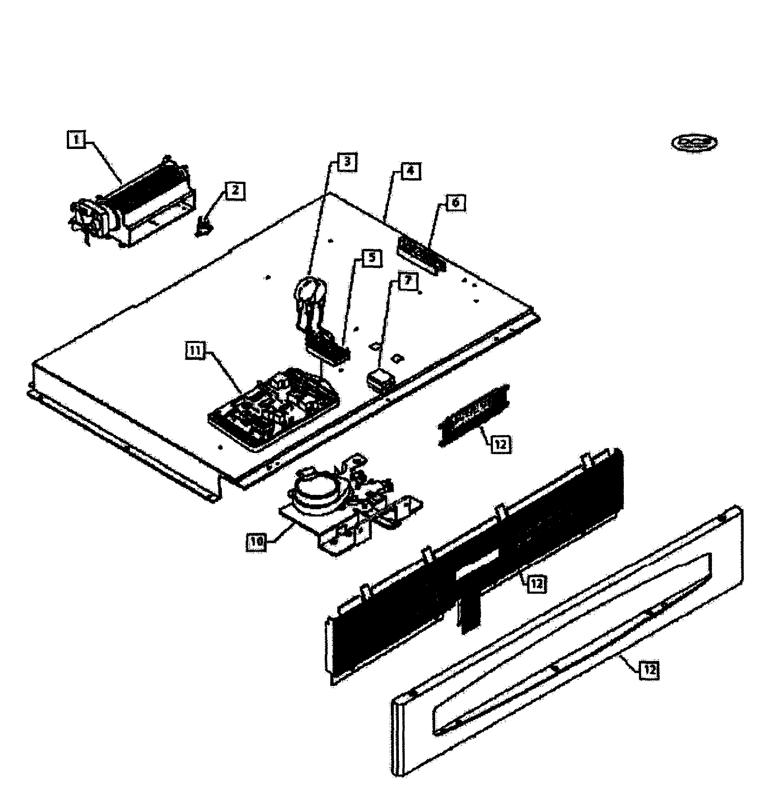
Dcs Wos 130ss Ph 70085 Electric Wall Oven Parts Sears
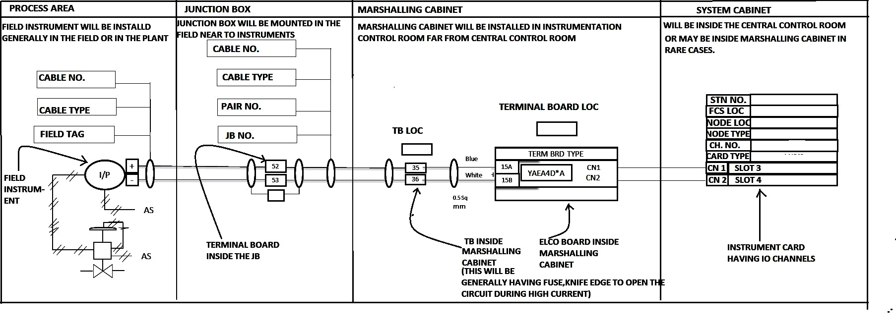
Dcs panel wiring diagram. Earth e or symbol. So we use internal wiring to route these main cablesfield devices from marshalling to system cabinet. The three phases are then connected to a power interrupter. This system uses 3 phase ac power l1 l2 and l3 connected to the terminals. When wiring ac supplies. Electrical house wiring 3 gang switch.
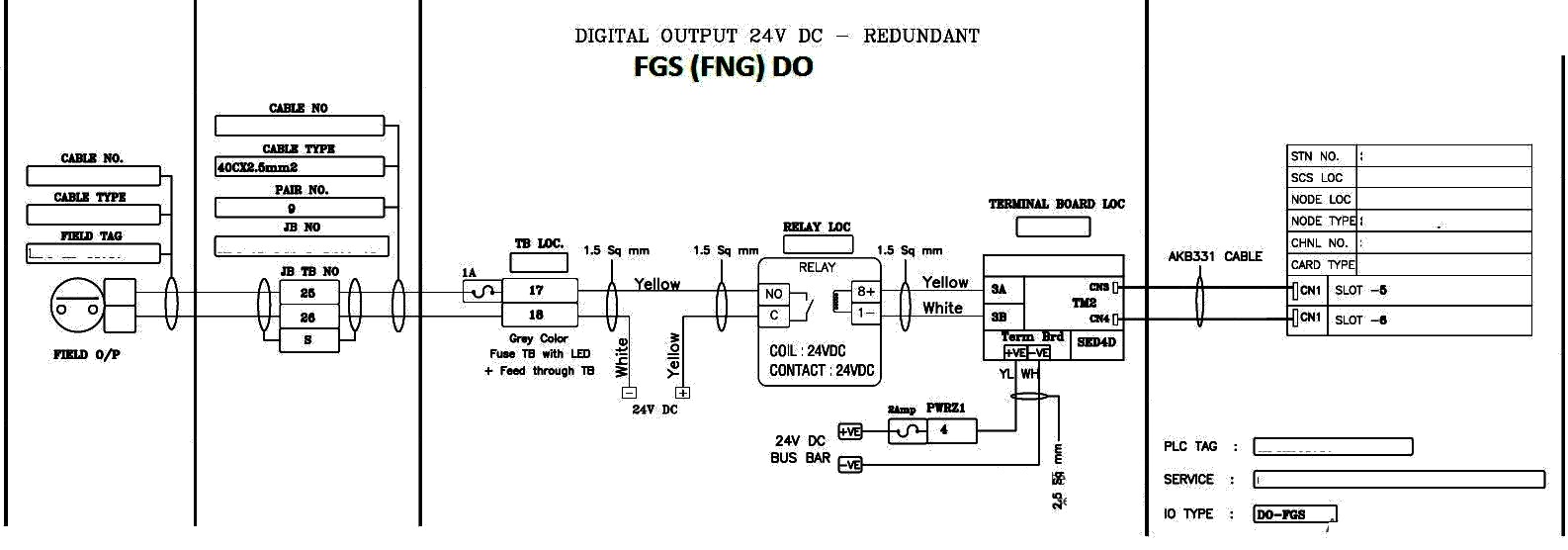
Once the main cables are connected to the analog input card via internal wiring and it converts the 4 20ma which is coming from field devices into equivalent digital signal ie. Dcsplc panel wiring diagram. In this article we are sharing the basic concepts of plc and dcs control systems wiring diagrams for digital input di digital output do analog input ai and analog output ao signals. If equipment that generates electrical noise or heat is positioned in front of the plc as when such equipment is mounted on the back of a panel door allow a clearance of 100 mm or more between the plc and such equipment. A distributed control system dcs is a specially designed automated control system that consists of geographically distributed control elements over the plant or control area. Dashed lines indicate a single purchased component.
An example of a wiring diagram for a motor controller is shown in figure 1. In binary codes and the same will be communicated to processor card. Note that these diagrams are without a barrier or isolator fuses and surge protector for keeping it very simple and understandable. Note that symbols are discussed in detail later.
