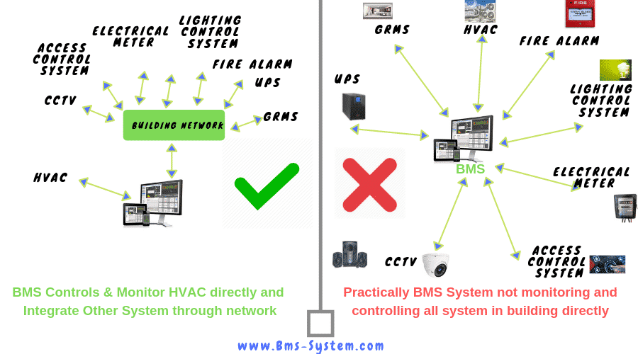
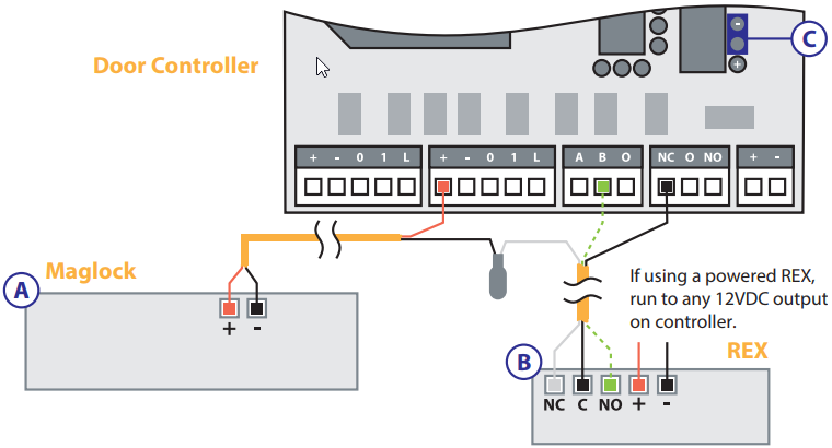
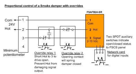
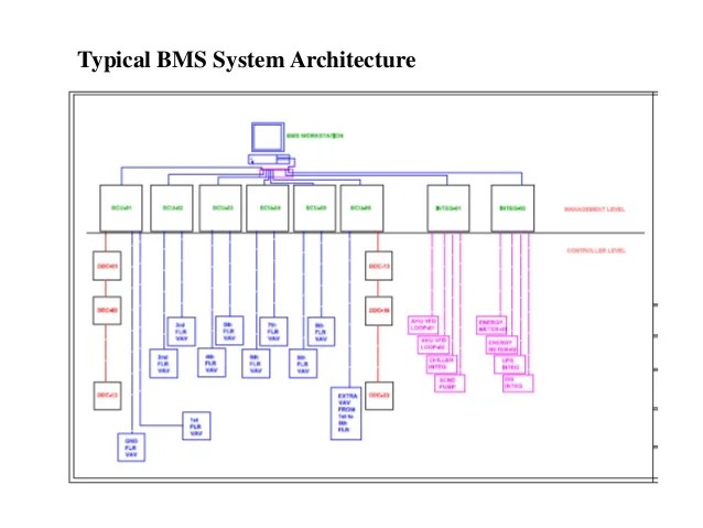
Vfd wiring details 11. Typical bms wiring interlock with the starter panel 8.

Detailed Drawings For Building Automation Systems In Chicago
Ddc panel wiring diagram. Valladolid capital of castilla leon medium size town car industry renault madrid spain france miguel de cervantes el quijote cristobal. Cabling between valve actuator ddc 24 core 1 or 15 sq mm 6. However a large building normally. Intent of battelle pacific nw division involvement 2. A silt tl lhih d ilt lignal to a control panel which sends a signal to a valve. Hvac and electrical 47641 views.
This diagram illustrates some of the most common circuits found in a typical 200 amp circuit breaker service panel box. Purpose of controls. Pnwd sa 8834 1 7 courtesy tac controlsschneider electric. A smaller building may have a single computerized hvac controller that operates the direct digital control ddc system. Page 21 oe217 02 g 0130l00118 e bus digital room sensor temp. This page contains wiring diagrams for a service panel breaker box and circuit breakers including.
Use with ddc controller only. Circuit breaker panel box wiring diagram. Differential pressure sensor wiring details 9. How to install ddc control panel. Connects to controller via fi eld wiring. System level cabling cat 6 cabling typical i o devices in hvac system 7.
Wiring diagram for bms ddc panel vnd592vxkglx. 3 fcu wiring 5 ahu flow diagram 6 ahu 1 wiring diagram cover page pittsburgh air systems inc. Part 1 hvac control principles 1. A custom made multi layer steel head gasket oem metal base gasket tensioner gasket and cam bolt lock plate and a procycle specific big bore cylinder sleeve. 15amp 20amp 30amp and 50amp as well as a gfci breaker and an isolated ground circuit. Building room pressure transducer wiring details 10.
Download view wiring diagram for bms ddc panel as pdf for free. Package air conditioning full wiring practical video very important video duration. Wiring diagram for bms ddc panel free download as pdf file pdf text file txt or view presentation slides online. The oe217 02 g is used with the ddc controller for room air temperature sensing applications. Woods 1 scale none job sheet 1 of 13 7 ahu 2 wiring diagram 9 boiler panel 10 boiler panel expansion. Only lcd display and keypad allow for setpoint adjustment override and display of certain status and setpoints.
Section 3 k c t. Calibrating and verifying energy savings of the ddc controls pnwd sa 8834 1 3. Ddc panel wiring diagram pdf.


