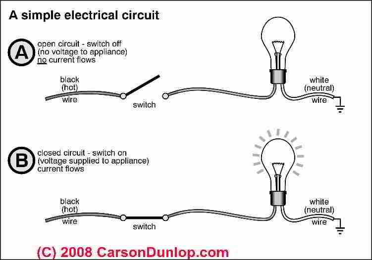
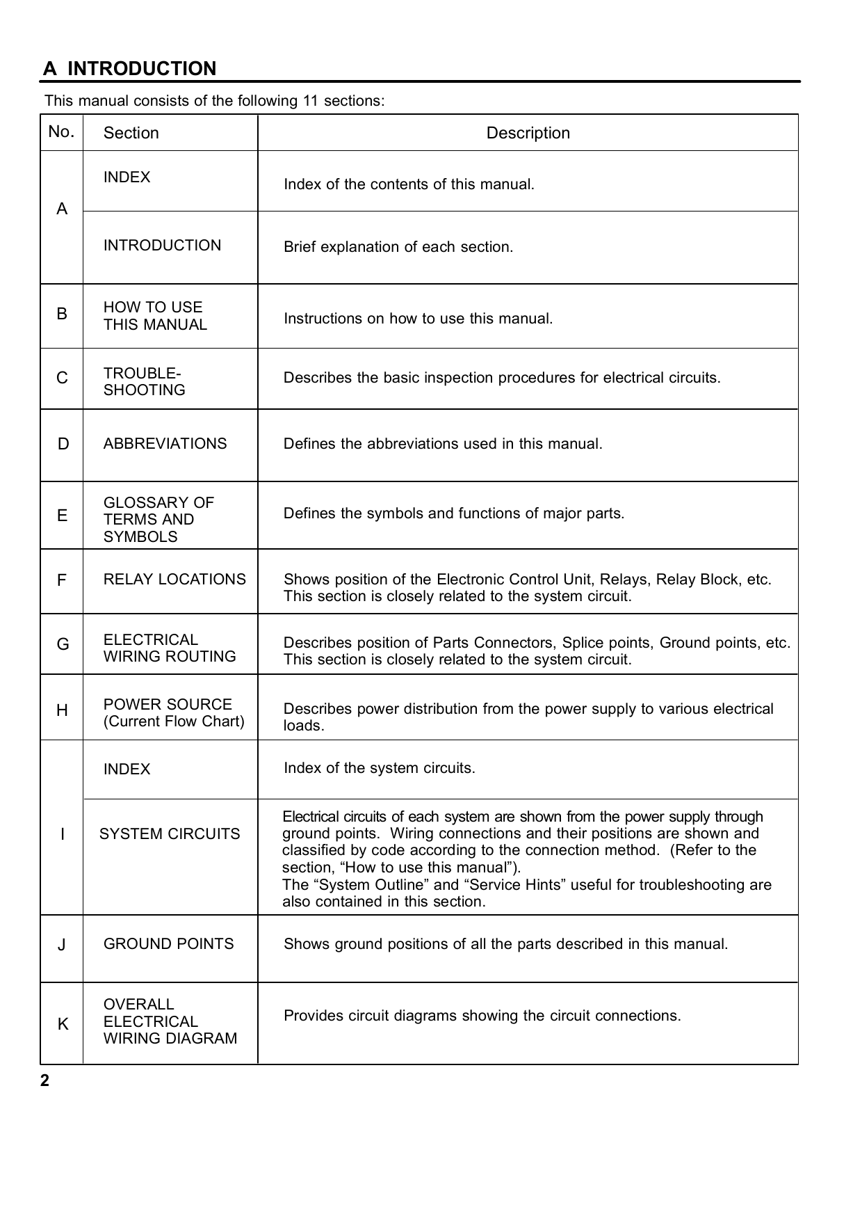
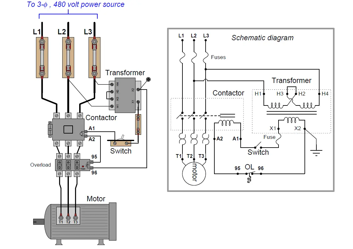
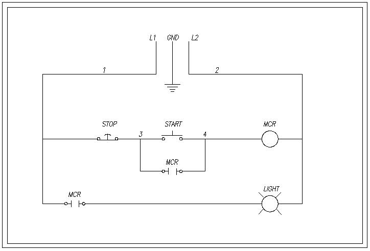
A wiring diagram is used to represent how the circuit generally appears. Electrician circuit drawings and wiring diagrams youth explore trades skills 3 pictorial diagram.
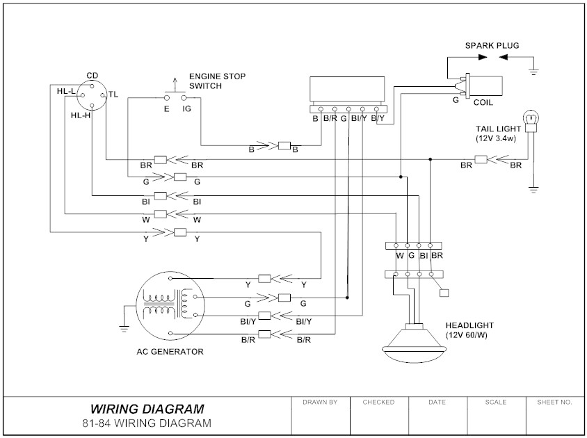
Wiring Diagram Everything You Need To Know About Wiring Diagram
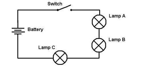
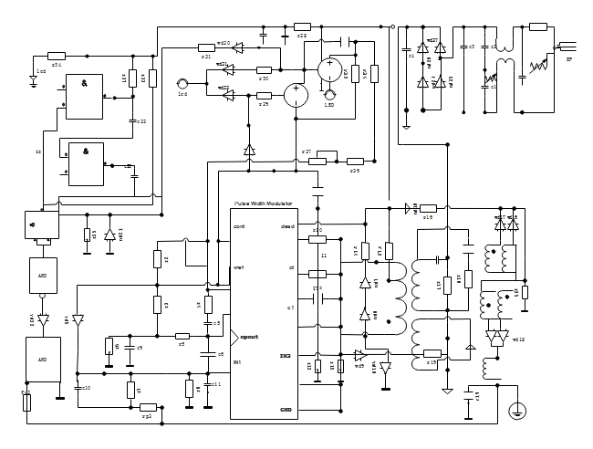
Describe the interpretation of circuit and wiring diagrams. Each electronic component has a symbolafter seeing a few circuit diagrams youll quickly learn how to distinguish the different symbols. A diagram that represents the elements of a system using abstract graphic drawings or realistic pictures. Understand the difference between schematics wiring diagrams and block diagrams and how each is used to describe circuit performance and function recognize common electrical component symbols and drawing conventions that describe circuits recognize and describe the configuration of common. Basic schematic interpretation learning objective actions. The best way to do this is to break the circuit down into smaller sections and study each section and develop a block diagram for the overall circuit. Reduce the circuit to a pure series or pure parallel circuit if it is a hybrid circuit.
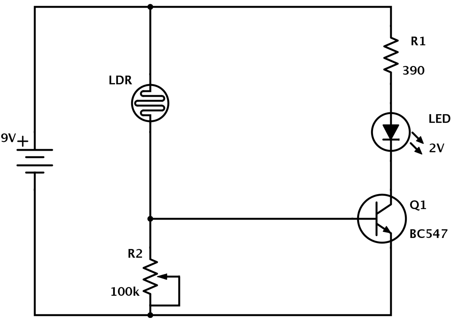
What is a circuit diagram. An electric circuit is a closed loop with a continuous flow of electric current from the power supply to the load. The presentation of the interconnections between circuit components in. A circuit diagram or a schematic diagram is a technical drawing of how to connect electronic components to get a certain function. How do you interpret circuit diagrams wiring diagrams and specifications used for the installation. A circuit diagram electrical diagram elementary diagram electronic schematic is a graphical representation of an electrical circuita pictorial circuit diagram uses simple images of components while a schematic diagram shows the components and interconnections of the circuit using standardized symbolic representations.
To help illustrate the differences between wiring diagrams and schematics a basic control circuit will first be explained as a schematic and then shown as a wiring diagram. Wire trace a circuit using the procedures. Combine resistors such as appliances to do this. Using some equations like vir or piv will allow you to calculate impedance current power and voltage in each part of the circuit. Describe the characteristics and circuit functions of electrical and electronic components used in army fire control instruments. Electric circuits like ac lighting circuit battery charging circuit energy meter switch circuit air conditioning circuit thermocouple circuit dc lighting circuit multimeter circuit current transformer.
Here are ten simple electric circuits commonly found around the home. For example if a circuit is mostly series but has two resistors in parallel with each other find the combined resistance of those two resistors and redraw the circuit with one new resistor rather than two. A diagram that uses lines to represent the wires and symbols to represent components. To include bs and iso schematics wiring regulations symbols. Wiring diagrams show components mounted in their general location with connecting wires. Identify the symbols used in typical schematic diagrams of army technical manuals.
