Line diagrams also called schematic or elementary diagrams show the circuits which form the basic operation of the controller. They are an ideal means for troubleshooting a circuit.

U208 Tic236 220v Ac Motor Controller Schematic Circuits
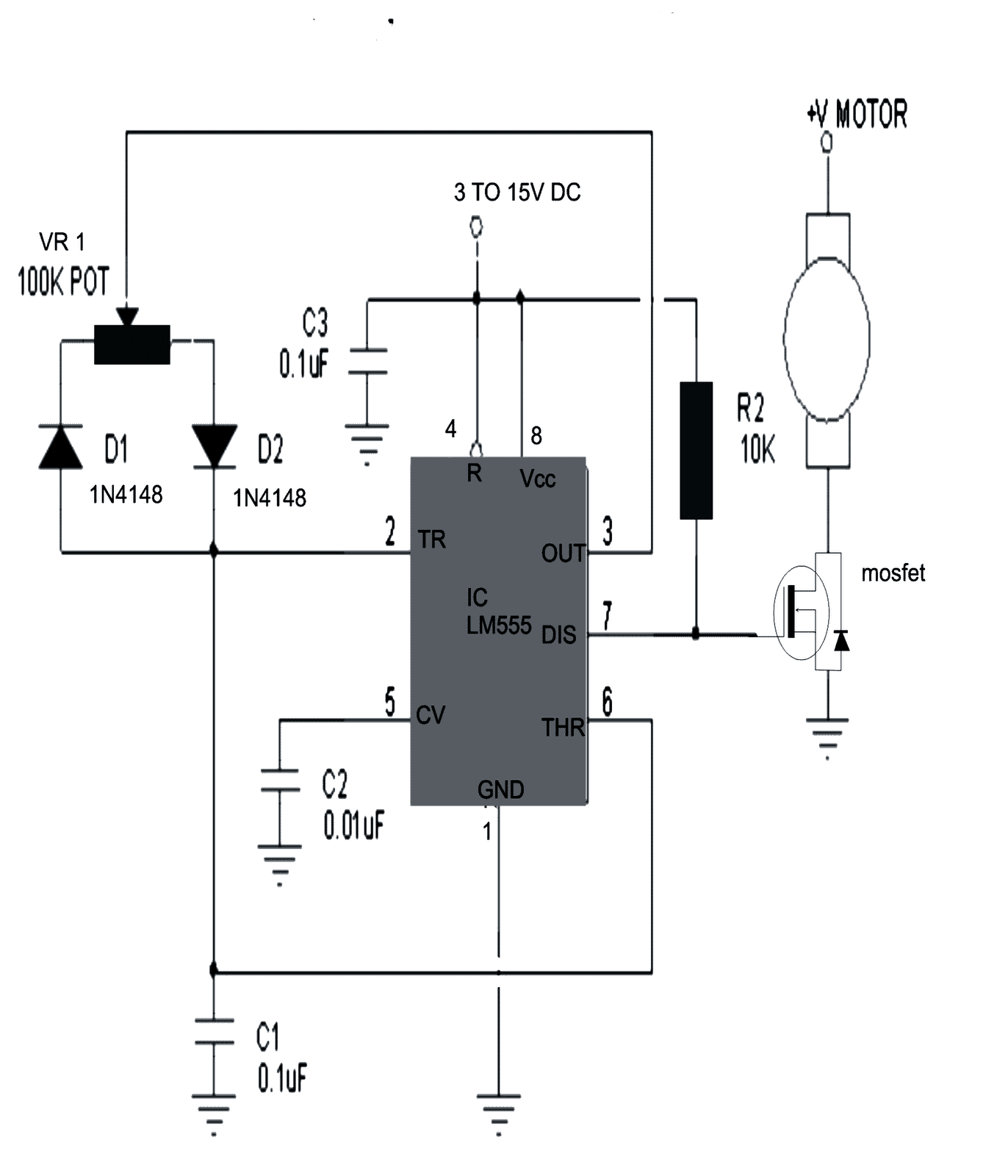
Diagram of motor control circuit. You may also read. We use 2 magnetic contactors as forward reverse switch. The manufacturers of motor control equipment for edu cational material and standard motor control circuits. This schematic shows both the control circuit and the motor circuit. 3 easy to build speed controller circuits for dc motors are presented here one using mosfet irf540 second using ic 555 and the third concept with ic 556 featuring torque processing. Based on your observations of these two diagrams explain how electromechanical relays are represented differently between ladder and schematic diagrams.
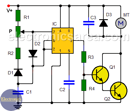
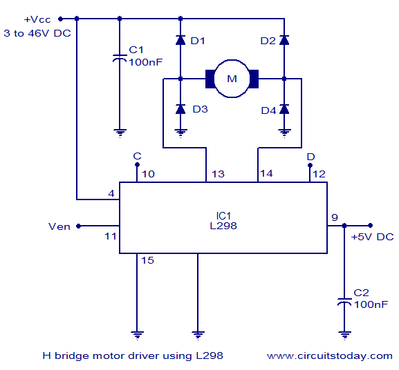
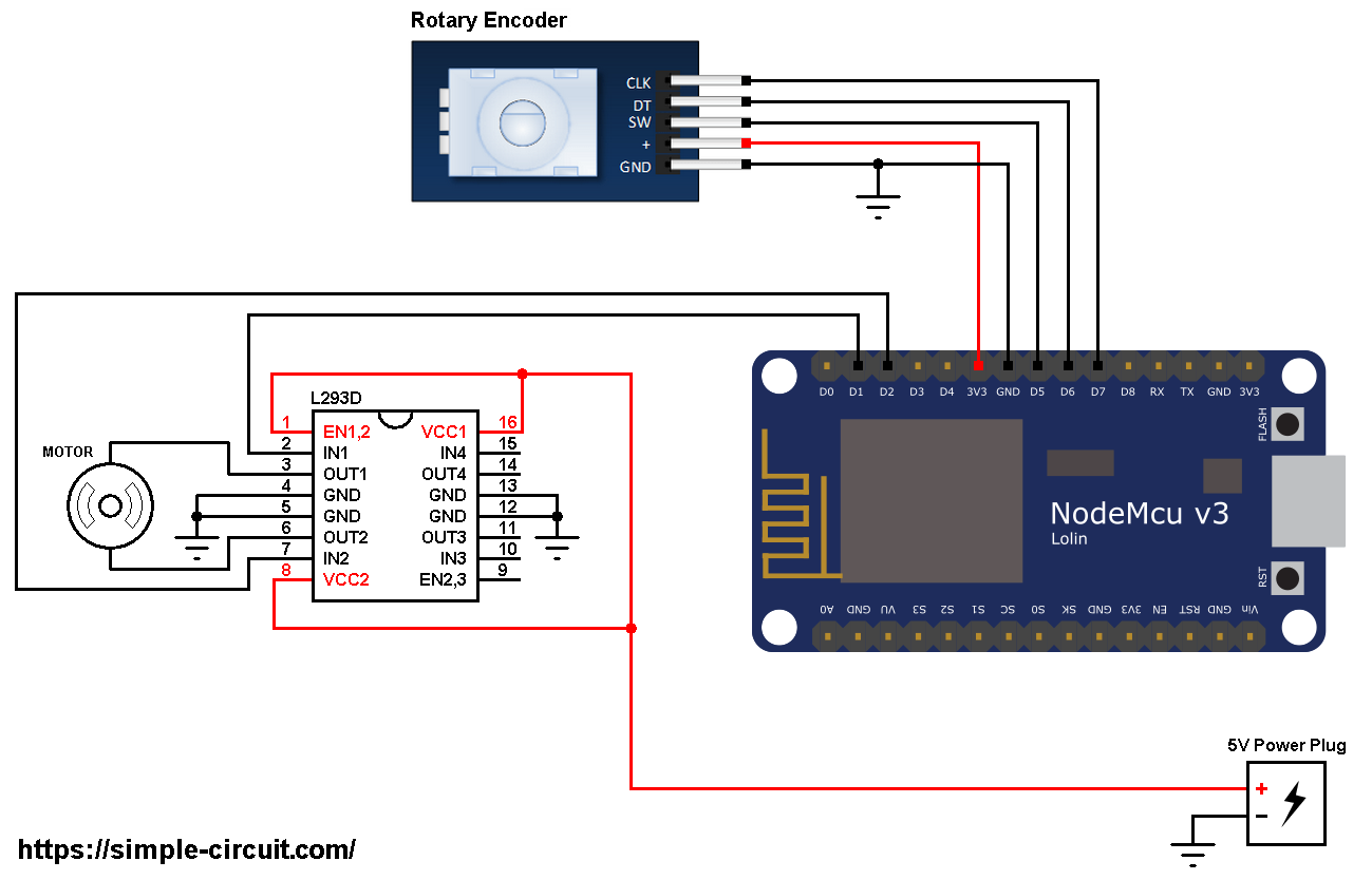
A circuit which enables a user to linearly control the speed of a connected motor by rotating an attached potentiometer is called a motor speed controller circuit. Interpret this ac motor control circuit diagram explaining the meaning of each symbol. Up tp 93 off launching official electrical technology store shop now. Figure 2 shows a typical line or schematic diagram. Already we discussed about the basics of permissive and interlock circuits in previous post also discussed about the basic motor control logic using forward reverse control. We could replace the push button switches with.
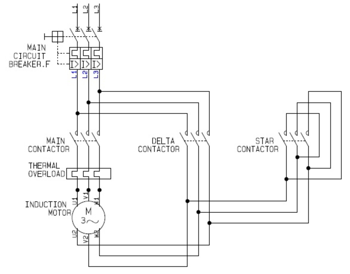
Also explain the operation of this motor control circuit. Three phase motor power control wiring diagrams 3 phase motor power control wiring diagrams three phase motor connection schematic power and control. They do not indicate the physical relationships of the various components in the controller. The interlock contacts installed in the previous sections motor control circuit work fine but the motor will run only as long as each push button switch is held down. If we wanted to keep the motor running even after the operator takes his or her hand off the control switches we could change the circuit in a couple of different ways. In the diagram i connect the incoming three phase supply l1 l2 l3 to the mccb circuit breaker molded case circuit breaker.
A simple circuit diagram of contactor with three phase motor. Figure 914 shows a start stop push button circuit. Unit 1conclusion this unit explained the basic concepts of motor con trols concentrating on how specialized electrical sym bols words and line diagrams are used to convey information about motor control circuits. Here i showed the forward reverse wiring diagram. Schematic diagrams do not always show both control and motor connections. Many schematic diagrams show only the control circuit.
The first circuit to be discussed is a basic control circuit used throughout industry. See more ideas about electrical diagram electrical circuit diagram electrical engineering. Forward reverse motor control diagram for three phase motor for three phase motor forward reverse control circuit. The interlock contacts installed in the previous sections motor control circuit work fine as discussed in previous article but the motor will run only as long as each pushbutton switch is held down. Feb 5 2020 explore elects agass board electrical diagram on pinterest.
Gallery of Diagram Of Motor Control Circuit