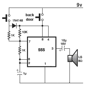
In the simplest design one of the solenoids hits a bumper instead of the second tone bar. This tutorial explains a simple circuit that produces ding dong sound using 555 timers.

How A Wired Doorbell Works Hometips
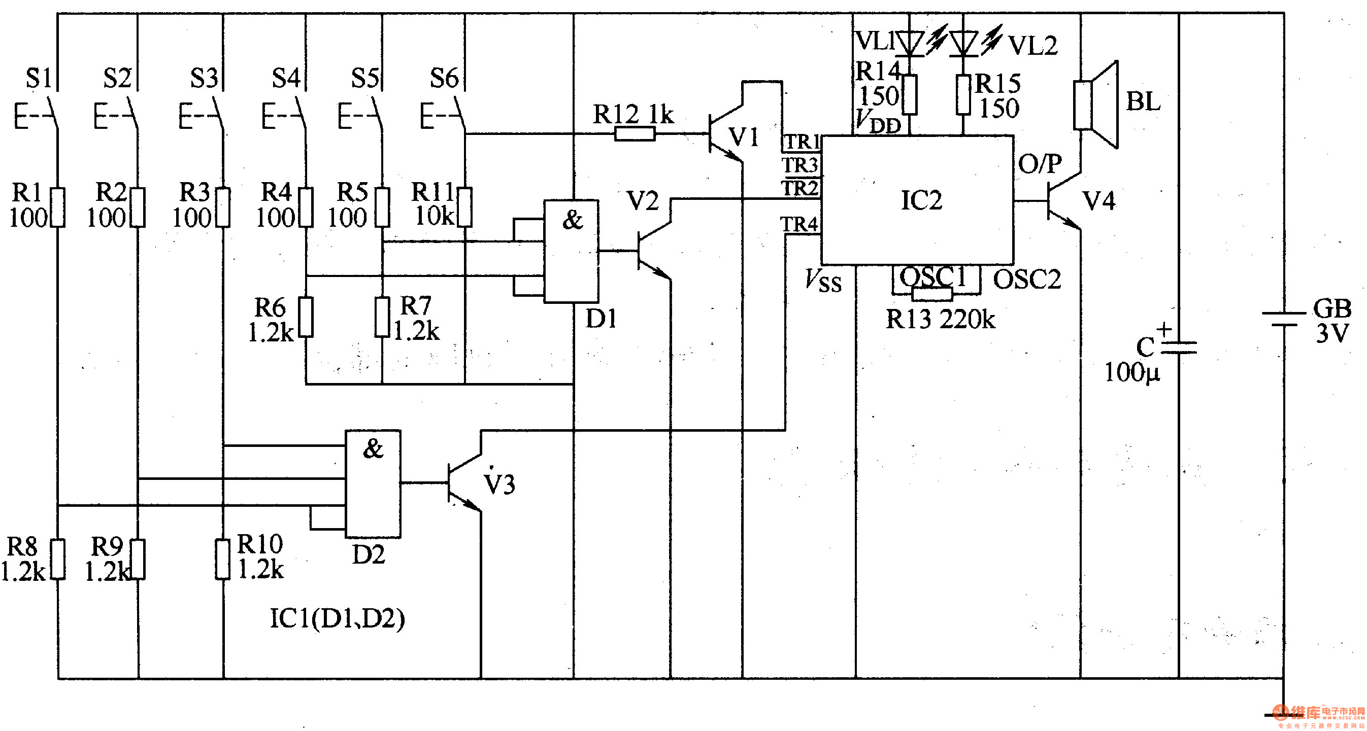
Ding dong doorbell circuit diagram. Each doorbell button closes a separate circuit connected to separate solenoids in the doorbell mechanism. The main feature of this doorbell is that we can control the time duration for which it keeps ringing upon pressing the. One can design their own doorbell using simple electronic components. It can be easily set up in your house just in case. To crease a square wave signal then send to amplify in the next. The sound is stored in the ic as bits as in a rom.
The ic has an in built circuitry to produce ding dong sound each time its pin 3 is pulled low. In circuit diagram as figure 1 will see that we use both transistor are connecting as the oscillator circuit on multi vibrator form. In this ding dong sound generator door bell circuit we have used two separate 555 timer ic to generate ding dong signal. Doorbell is a very common and useful device used in every household. Door bell circuit door bell circuit. Ding dong bell sound generator circuit design.
In this way one doorbell button will trigger a ding dong tone and the other button will trigger only a ding tone. This ding dong door bell circuit might become the simplest and cost effective door bell circuit. It is an 8 pin dip dual inline package ic whose only four pins as shown in the above circuit design have been used. The working principle of circuit. Circuit diagram and explanation. And a 10k r4 resistor 50k pot rv1 between pin 7 and 6.
The ic has an in built circuitry to produce ding dong sound each time its pin 3 is pulled low. This simple and cost effective ding dong electronic doorbell circuit is based on ic 8021 2. The circuit consists of two 555 timer ics arranged as shown in the circuit diagram. In first 555 timer ic we have connected a 1k r1 resistor between vcc pin 7th of 555 timer u1. The first timer ic is connected in astable mode to produce pulse of frequency 1hz. So in this tutorial we are going to build a doorbell with 555 timer ic.
The circuit is designed based on single ic 8021 2 which manufactured formox semiconductors. The sound is stored in the ic as bits as in a rom. Among electronics students and hobbyists doorbell circuit project is quite popular. The sound output from the ic cant however drive a speaker directly as this puts strain on the device. Ding dong sound generator doorbell circuit using transistors. It is an 8 pin dip ic whose only four pins as shown in the circuit have been used.


