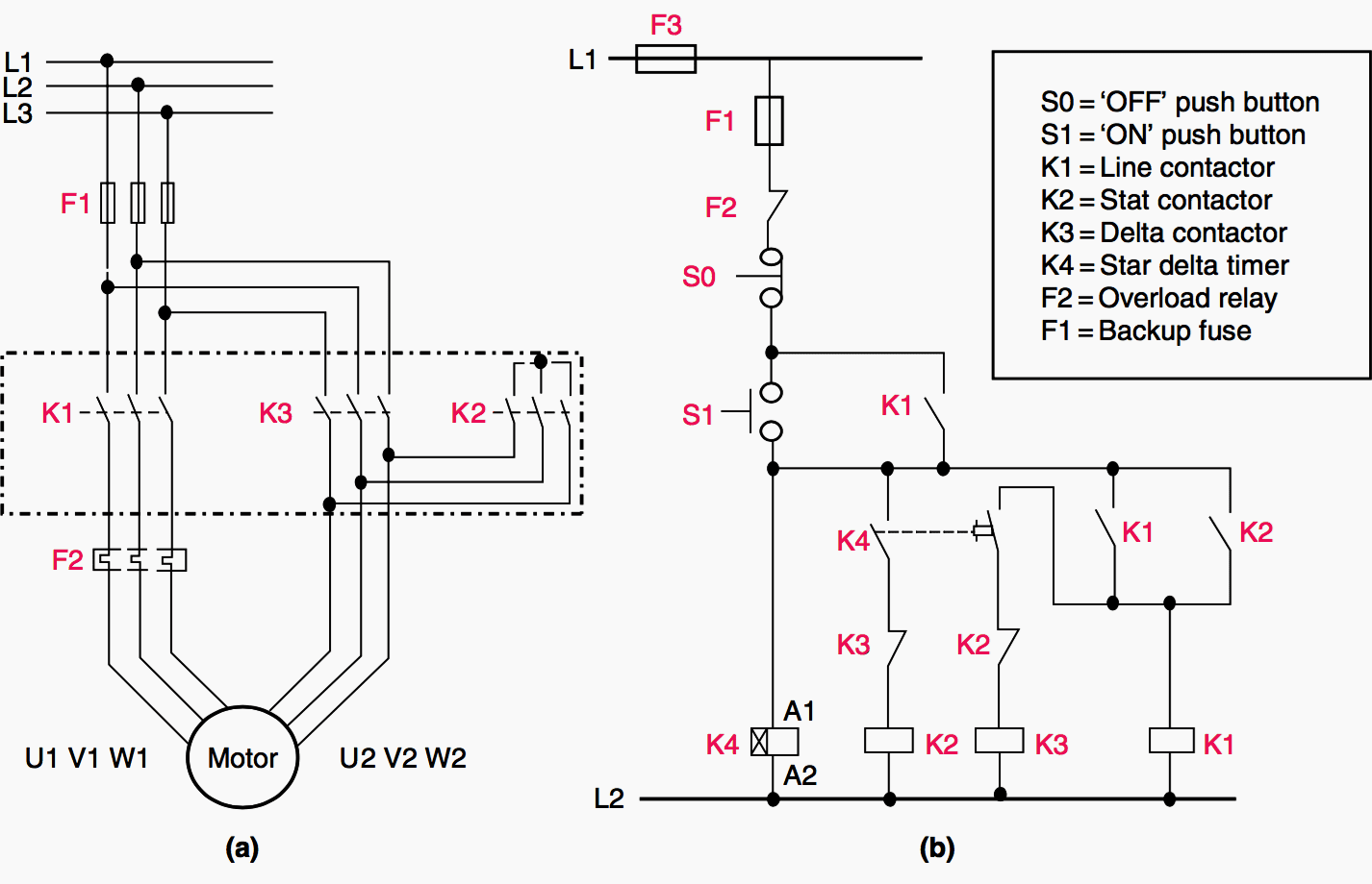
Three phase motor control and design power circuit and installation. Schematic and circuit diagram.

Dol Starter Direct Online Starter Diagram Amp Working
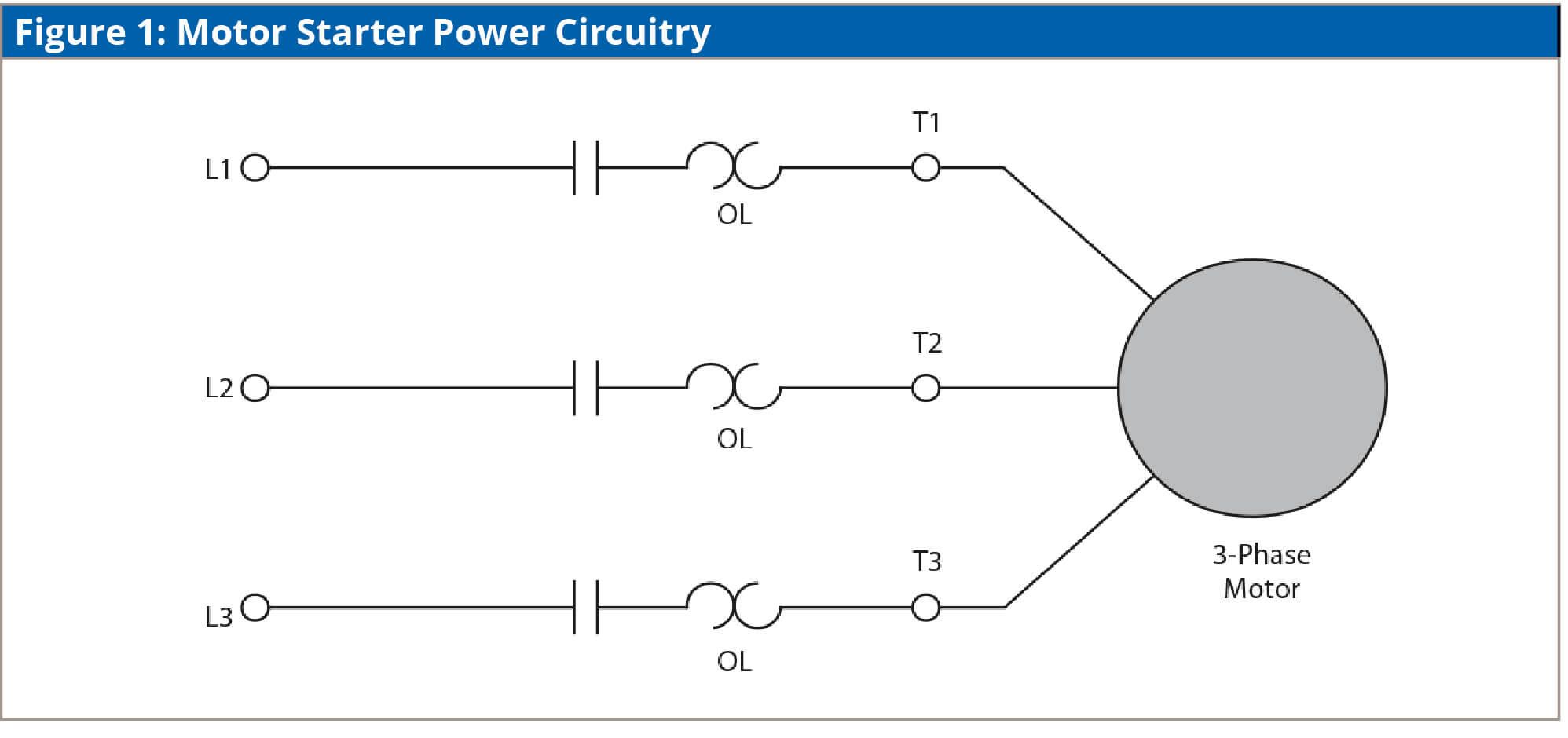
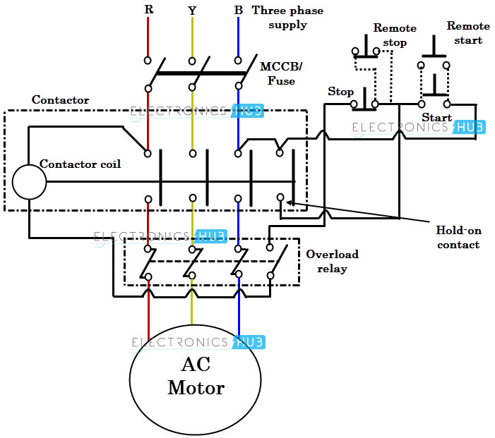
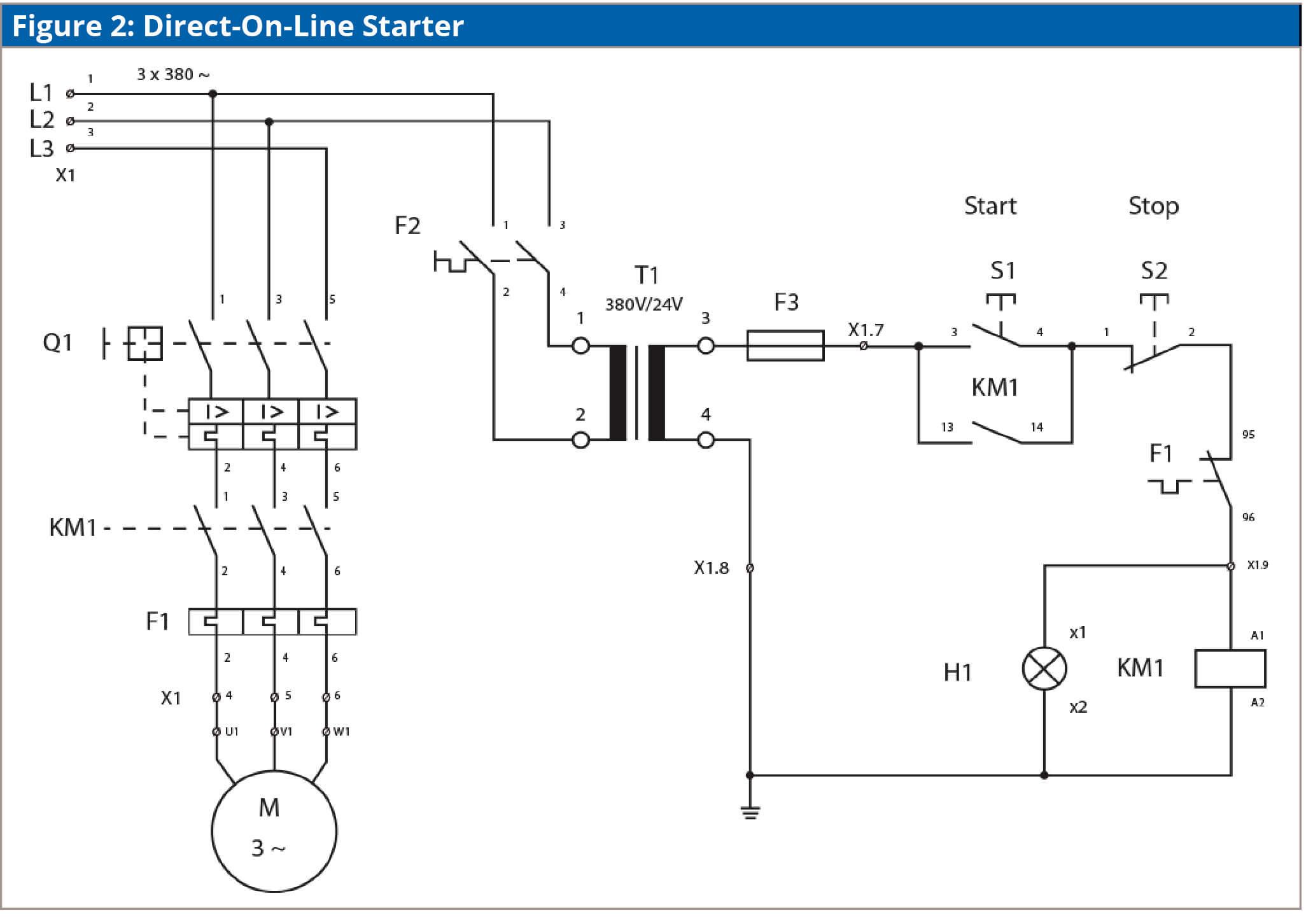
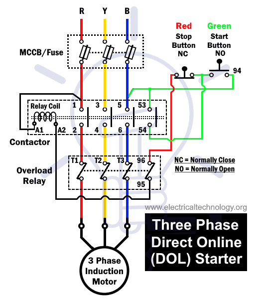
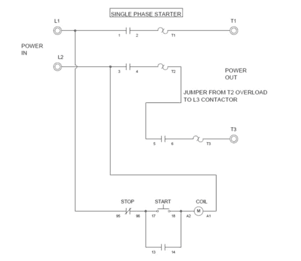
Dol starter power and control circuit diagram. The contactor is used for starting and stopping the motor where the green and red buttons are connected. The working principle of a dol starter begins with the connection to the 3 phase main with the motor. Direct on line starter. Three phase and single phase. Sometimes known as an across the line starter this type of motor controller is used as a simple starter for larger electric motors providing. I dol starter wiring connection with start and stop buttons are shown in the above figure 1.
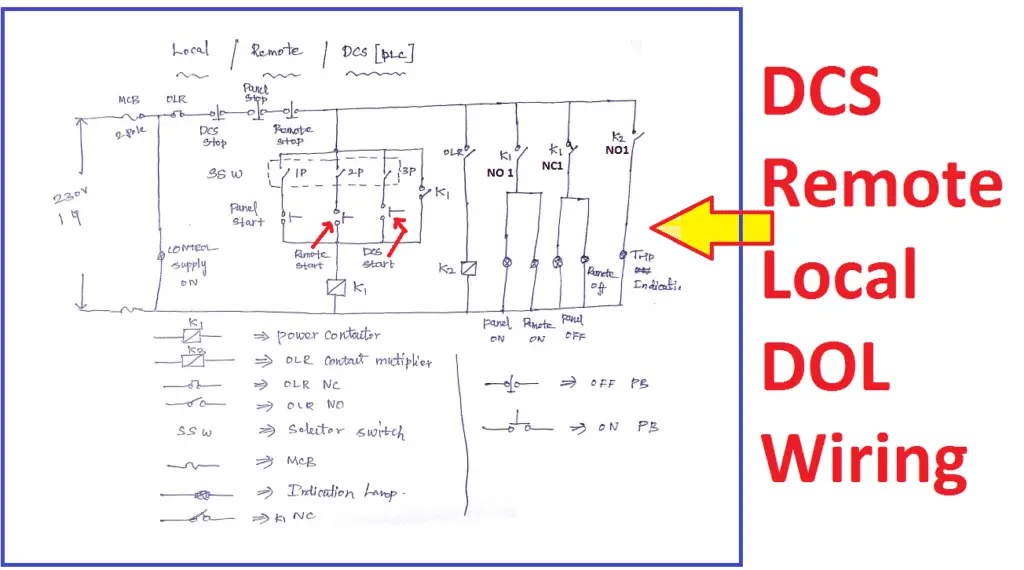
Dol starter working principle. The circuit breaker is used for protection against short circuits while the overload relay protects the motor from overloading. All controlling of starter are controlled by this circuit. Between the mains supply terminals and motor terminals the dol starter main terminals are connected and with the two terminals of the three phase power supply as described in figure 1 the control circuit is energized. The dol starter is made of a circuit breaker or mccb or fuse an overload relay and contactor or coil. Dol starter control circuit diagram consist components like main power contactor start button stop push button and overload relay is connected in series this circuit is called control circuit of dol motor starter.
When we press the start button the current flows through contactor coil magnetizing coil and control circuit also. The control circuit is connected to any two phases and energized from them only. A dol starter is a direct on line motor starter.


