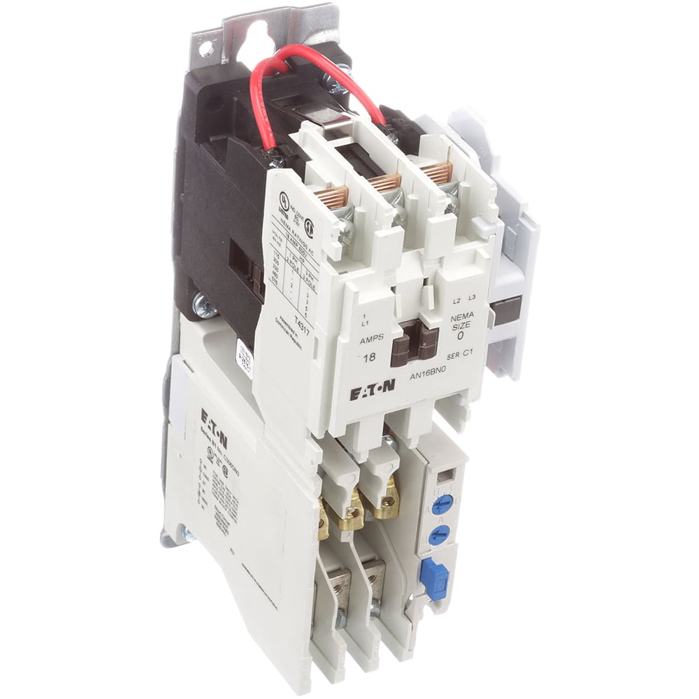
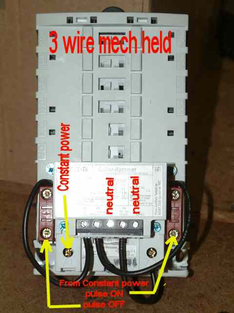
Mac valve wiring diagram valid eaton wiring diagrams wiring diagram. A wiring diagram is a streamlined traditional photographic representation of an electric circuit.

7101 Eaton Iec Motor Starter Wiring Diagram Wiring Library
Eaton motor starter wiring diagram. Eaton motor starter wiring diagram whats wiring diagram. Basic wiring for motor contol circuitry of a starter two wire control two wire control circuits or low voltage release one of the common control wiring circuits used is known as two wire or low voltage release lvr. 3ph starter3ph motor line voltage control three phase 3ph motor starter controlling a three phase motor rev 08 aug 2006 the above wiring diagram assumes your magnetic starter has a 240v coil. It utilizes a main tained contact type of pilot device such as a thermostat float switch or presence sensor. Cutler hammer motor starter wiring diagram collections of magnetic starter diagram beautiful cutler hammer motor starter. Collection of eaton motor starter wiring diagram.
Wiring diagram cutler hammer motor starter fresh magnetic starter. A motor starter is a combination of devices used to start run and stop an ac induction motor based on commands from an operator or a controller. It reveals the components of the circuit as streamlined shapes and also the power as well as signal connections in between the tools. Wiring diagram practice simple magnetic starter diagram beautiful. In north america an induction motor will typically operate at 230v or 460v 3 phase 60 hz and has a control voltage of 115 vac or 24 vdc. If you have a 120v coil instead of running a line from coil overload l2 you must run coil overload neutral.
A wiring diagram is a kind of schematic which utilizes abstract photographic symbols to show all the interconnections of parts in a system.


