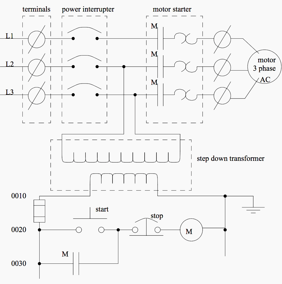
I explained the panel with single line diagram and control circuit diagram. Assortment of electrical control panel wiring diagram pdf.

Ats Panel Genset Controller In Relay Panel Wiring Diagram
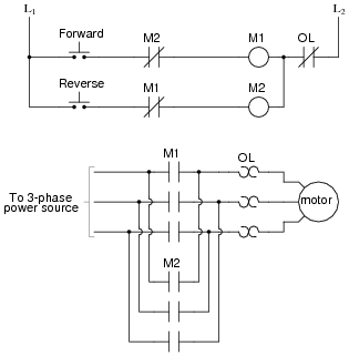
Electrical motor control panel wiring diagram. Electrical wiring diagrams of a plc panel. In this video i have explained you about a motor control panel which has 13 dol starters for operating 13 pumps. Schematics are generally easier to read and understand than wiring diagrams. Variety of motor control panel wiring diagram. Forward reverse motor control diagram for three phase motor for three phase motor forward reverse control circuit. We use 2 magnetic contactors as forward reverse switch.
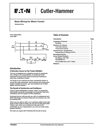
It reveals the parts of the circuit as streamlined shapes and the power and also signal links in between the gadgets. Feb 5 2020 explore elects agass board electrical diagram on pinterest. A wiring diagram is a simplified traditional photographic representation of an electrical circuit. Wiring diagrams wiring diagrams show components mounted in their general location with connecting wires. Basic wiring for motor control technical data. The simplest form of motor starter for the induction motor is the direct on line starter.
A wiring diagram is a streamlined traditional photographic representation of an electrical circuit. Star delta y δ 3 phase motor starting method by automatic star delta starter with timer. See more ideas about electrical diagram electrical circuit diagram electrical engineering. All critical safety functions should be hardwired this way. A wiring diagram is. Three phase motor connection schematic power and control wiring installation diagrams.
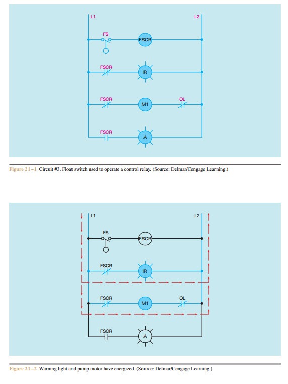
Wiring diagrams show the connections to the controller. Schematic diagrams schematic diagrams show components in their electrical sequence without regard for physical location. Schematic diagrams are used to troubleshoot and install control circuits. Here i showed the forward reverse wiring diagram. Three phase motor connection stardelta without timer power control diagrams. It shows the elements of the circuit as streamlined shapes and the power and signal links between the gadgets.
This figure shows the e stop wired to cutoff power to all of the devices in the circuit including the plc. Figure 5 below shows a schematic diagram for a plc based motor control system similar to the previous motor control example. The dol starter consist a mccb or circuit breaker contactor and an overload relay for protection. Wiring diagrams sometimes called main or construction diagrams show the actual connection points for the wires to the components and terminals of the controller. In the diagram i connect the incoming three phase supply l1 l2 l3 to the mccb circuit breaker molded case circuit breaker.


