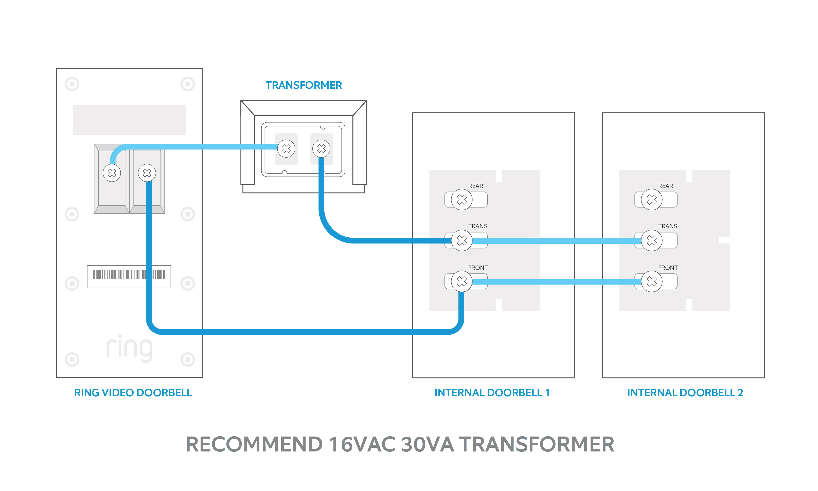
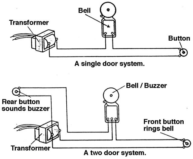
Wiring diagram for a two chime doorbell. Wiring for two doors is the same as for one with the transformer hardwired to the 120 volt source from a house circuit.
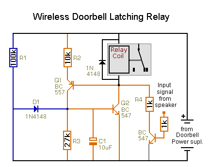
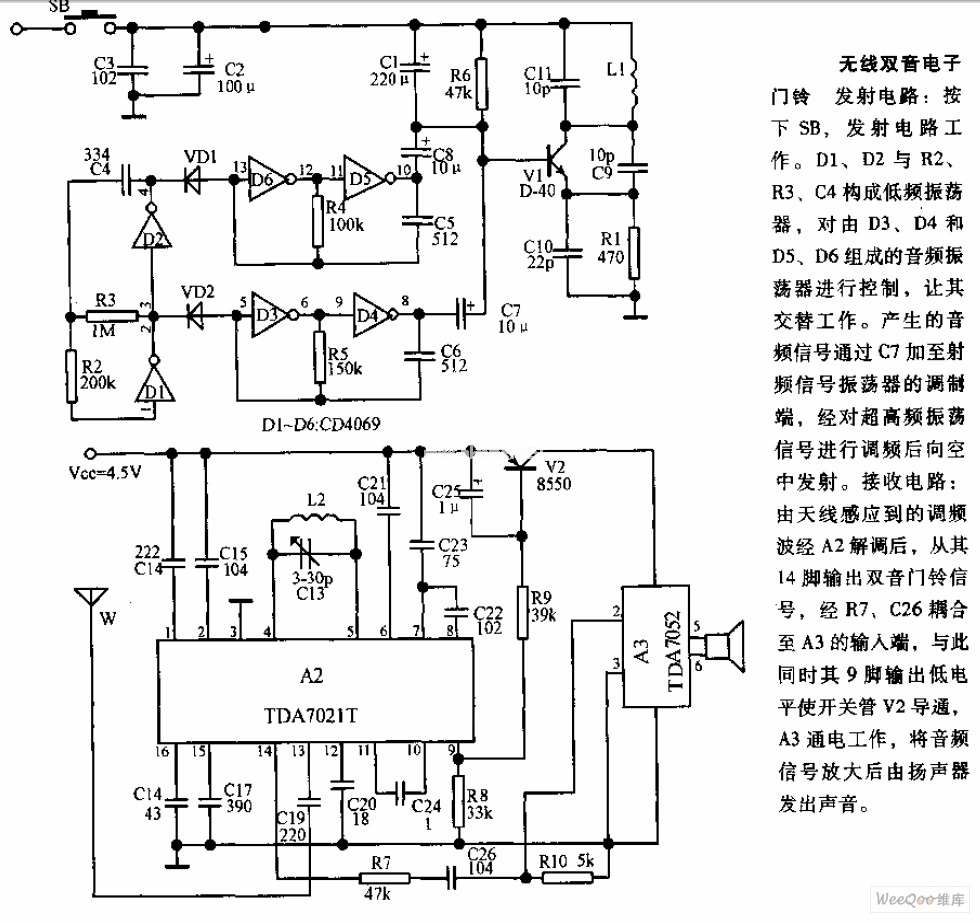
Wireless Doorbell Circuit Amp Re Wireless Doorbell To Operate
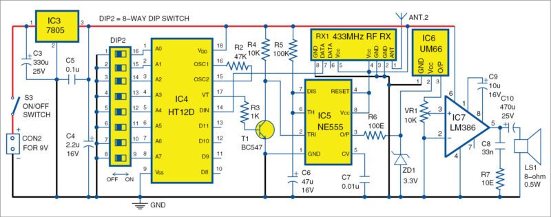
Electronic doorbell circuit diagram. A 750 kω is connected between the oscillator pins pins 15 and 16 of the ht 12e. Other connections are shown in the circuit diagram. T1 the lt700 tony van roons or equivalent is a small center tapped tony van roons ct audio transformer with an impedance of 1000 ohms at 1000 hertz. Connect the input wires on the transformer to the source circuit using the black to black white to white and ground to green method. Listening same door bell tune at always may be boring this melody generator doorbell circuit may help us to avoid this dull situation because this circuit provides 12 tonesthis multi tone door bell circuit produces 12 types of musical toneyou get twelve popular tones in sequences that gives a new dimension to musical door bells. This is why the circuit diagram of doorbell books that we supplied usually the books with remarkable motives.
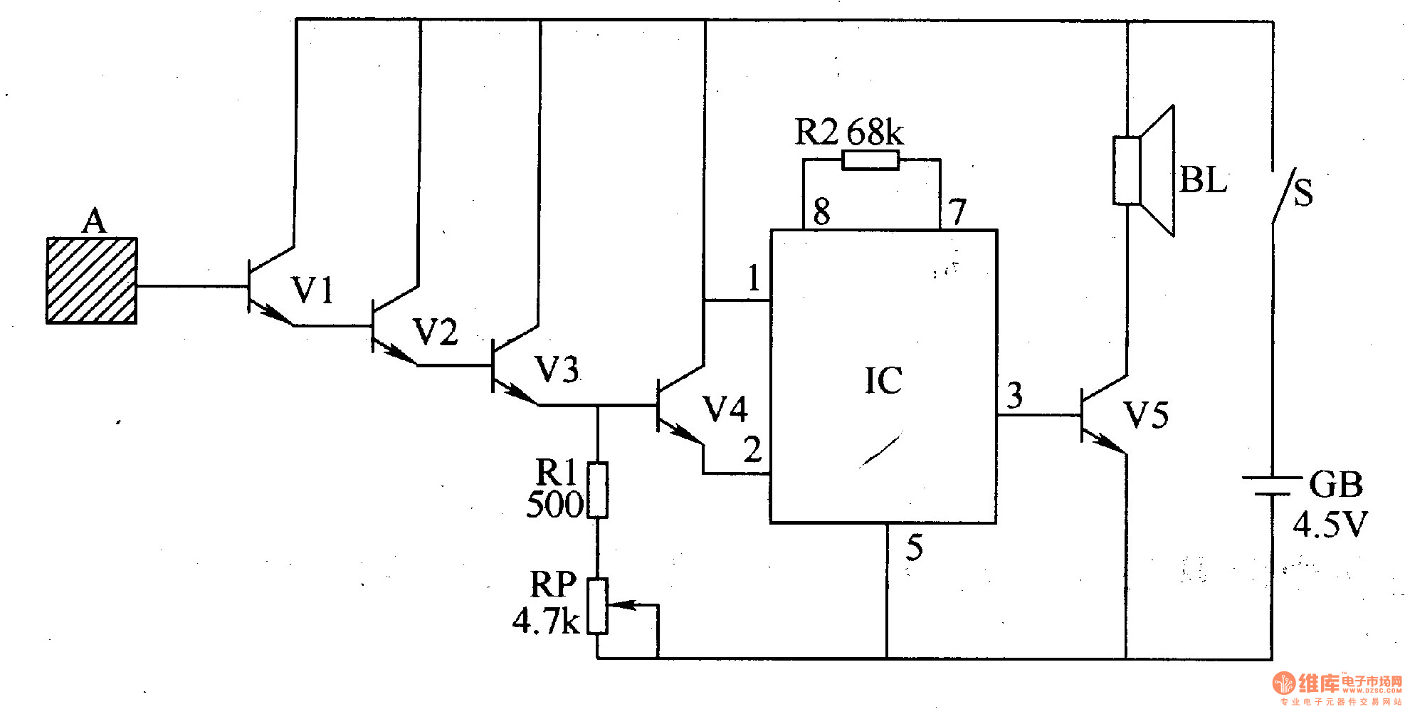
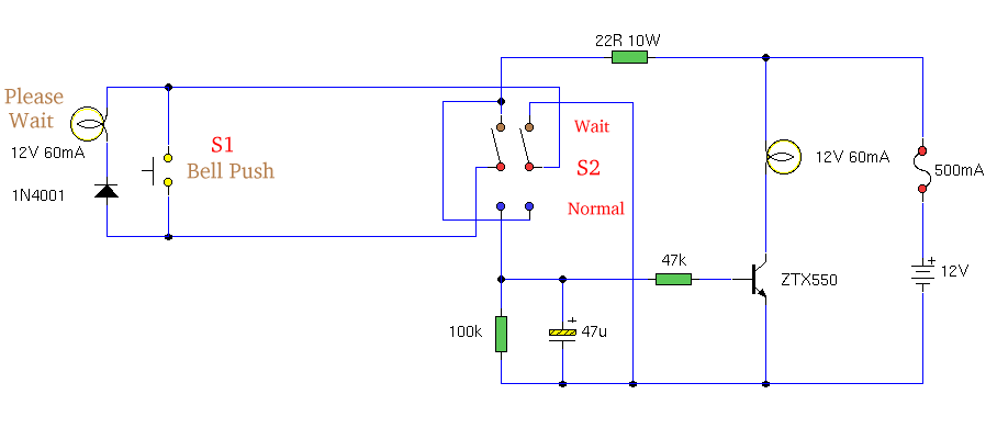
The sound is stored in the ic as bits as in a rom. The ic has an in built circuitry to produce ding dong sound each time its pin 3 is pulled low. Design of receiver circuit. Among electronics students and hobbyists doorbell circuit project is quite popular. There are many other benefits of the project doorbell. The circuit for the electronic doorbell here will help realise whether the visitor is in front door or in back door.
This musical doorbell circuit uses um3481 a series ic. The secondary of this transformer has an impedance of 8 ohms. Friends in this video i will show you how to make a mini powerful doorbell circuita simple musical doorbellmelodious ringing bell soundfriends it is a very simple circuit and you can easily. The main feature of this doorbell is that we can control the time duration for which it keeps ringing upon pressing the. Delivering proper book for the readers is kind of satisfaction for us. This simple and cost effective ding dong electronic doorbell circuit is based on ic 8021 2.
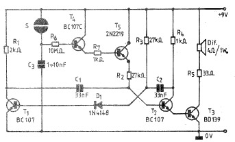
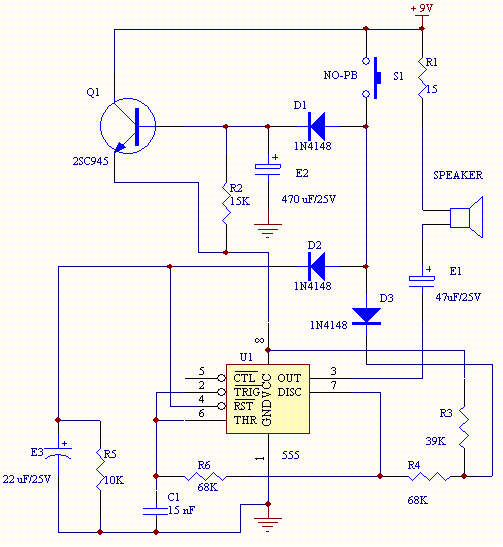
So you could examine circuit diagram of doorbell effortlessly from a few tool to maximize the generation usage. Doorbell is a very common and useful device used in every household. A push button is connected between ad8 pin 10 and ground. So in this tutorial we are going to build a doorbell with 555 timer ic. Electronic canary doorbell this circuit is a modified hartley oscillator with a couple extra parts. It is intended for applications such as toys door bells music boxes melody clocktimers and telephones.
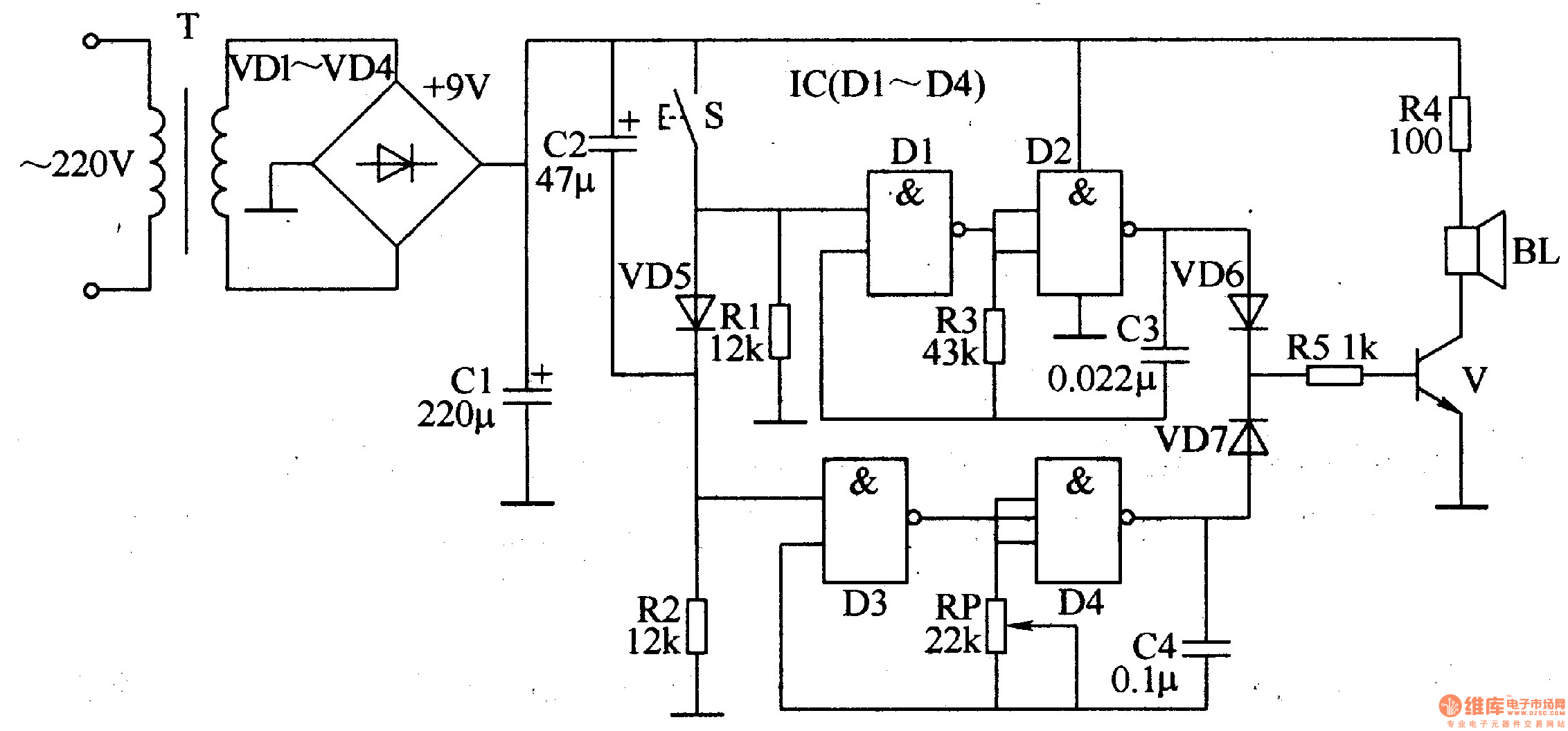
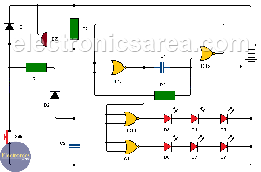
You can take it in the sort of soft document. The transmission enable pin pin 14 is connected to ground. The electronic doorbell in this article is the most simplest among the advance projects in this website. Musical doorbell circuit diagram.

