Another way of remembering the color coding is to simply switch the green set of wires in place with the orange set of wires. The way it works is incredibly simple.

Basics Of Ethernet Switches
Ethernet switch diagram. Grey represents unused wires. Both devices will be limited by the 100 mbits ceiling on the switch. Most but not all ethernet hubs and switches support up to four connections. This ethernet switch can. Instead of turning something on or off a network switch determines which of several tracks a particular packet of information should be sent to. In other words think of the red and grey lines on the top as one ethernet cable and the blue and grey lines on the bottom as another ethernet cable.
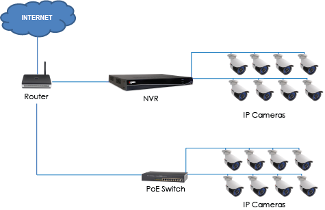
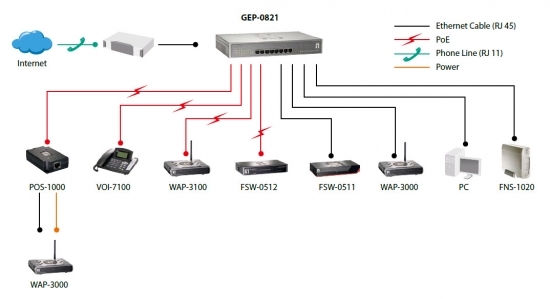
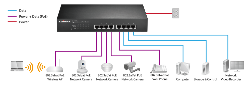
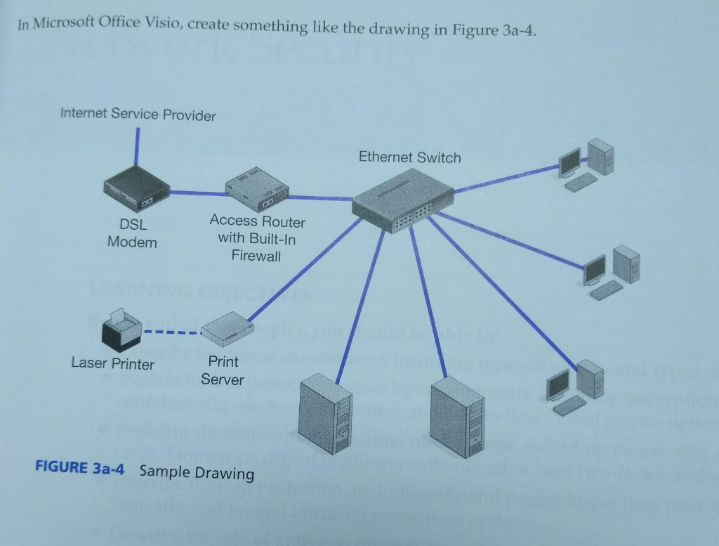
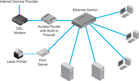
Modular connector plug and jack pin out ethernet cable pin outs. This diagram illustrates the use of an ethernet hub or switch on a home network. Ethernet hubs and switches allow several wired computers to network with each other. And thats exactly what an ethernet splitter does. The ethernet switch can also be wired to the router via a cable that plugs into an ethernet port which allows you to access the internet through the modem. Whether you have a four port switch or an eight port one you use one port to connect the switch to your router via ethernet then the rest into the other ethernet.
While some routers are manufactured as a network switch and router combo a router on its own performs a separate function from the switch even though sometimes they are found in a single. In an ethernet cable there is 8 wires but only 4 are being used. Lets also say these 4 wires occupy the slots 1 2 3 and 4 on the ethernet jack. Lets say the 4 wires being used are the two brown and the two orange. Returning to our original topic of turning one ethernet cable into two the ethernet switch is the real star of this guide. In the diagram below the red wires represent data connection a and the blue wires represent data connection b.
The 4 remaining wires are two green and two blue which occupy the slots 5 6 7 and 8 on the ethernet jack. There are two basic ethernet cable pin outs. A straight through ethernet cable which is used to connect to a hub or switch and a crossover ethernet cable used to operate in a peer to peer fashion without a hubswitch. For example lets say you have a media server in your basement with a gigabit ethernet card installed and a media console in your living room with a gigabit ethernet card but you are connecting the two together with a 10100 switch. Rj 45 crossover ethernet cable. Here is a wiring diagram and pin out.
In networking a switch is a device that receives incoming packets of information from the network and determines where each packet should be sentin that sense a network switch is more like a railroad track switch than a light switch. Its internet splitter provides connectivity to your modem or gaming router allowing for additional wired connectionsbe it an extra laptop a printer or your gaming console. A good way of remembering how to wire a crossover ethernet cable is to wire one end using the t 568a standard and the other end using the t 568b standard. Ethernet switch hub network diagram. The netgear gs1088 port gigabit ethernet unmanaged switch is the best ethernet switch for the unpretentious network builder who just wants to split a single connection between various devices.
:max_bytes(150000):strip_icc()/wired-diagram-3-58073d293df78cbc28f5ba06.jpg)

