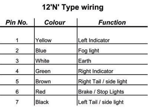
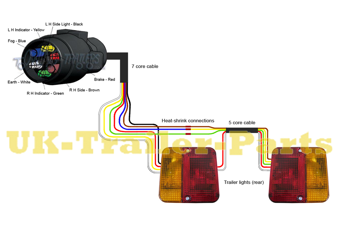
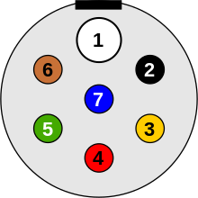
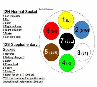
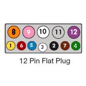
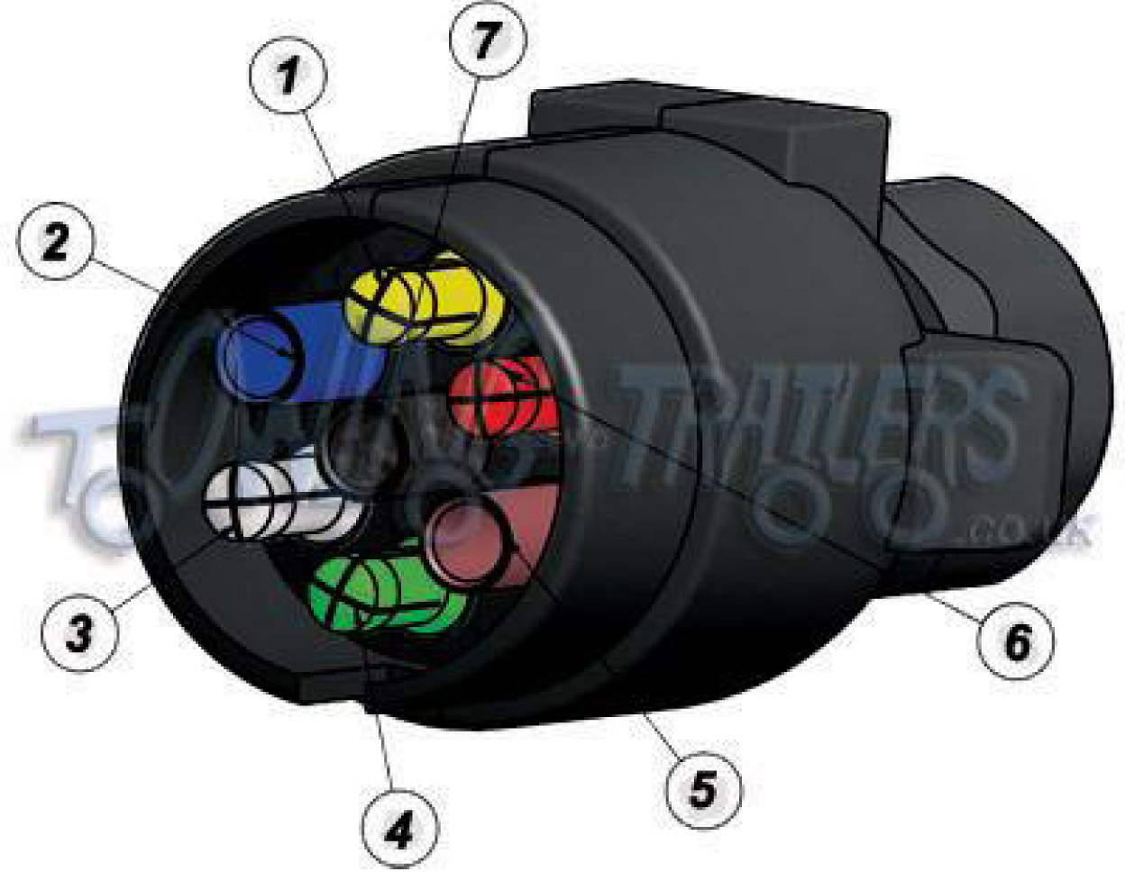
Blue electric brakes or hydraulic reverse disable see blue wire notes below in the trailer wiring diagram and connector application chart below use the first 5 pins and ignore the rest. Below is a diagram for the original plug and socket showing the functions of each pin.
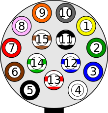
Iso Standards For Trailer Connectors Wikipedia
Euro trailer plug wiring diagram. Note that this type of 4 pin connector is less common that 4 pin flat connector. 4 way trailer connectors are typically used on small trailers such as boat snowmobile utility and other trailers that that do not use brakes. Four pin trailer wiring install wiring diagram info in electric by magnus sellén 9 august 2019 leave a comment many people often have difficulties with the wiring of their trailer and even after several attempts they still dont seem to get it right. This type of connector is normally found on utvs atvs and trailers that do not have their own braking system. This has now been replaced by 13 pin euro plugs on all new caravans. On the rear of the pins the numbers are marked in the plastic next to each pin.
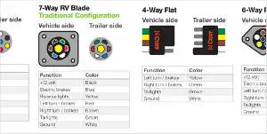
Below is the generic schematic of how the wiring goes. They also provide a wire for a ground connection. 4 pin trailer wiring diagram. This article will be talking euro trailer wiring diagram. Ive added a pair of diagrams which is going to show you the functions of each connector. 1 4 wire the first 4 pins white brown yellow green just like the 4 pin connector above.
Below is a diagram of a 13 pin euro trailer plug with coloured pins as they are wired. The 7 pin n type plug and socket is still the most common connector for towing. This supplies power to the road lighting of your trailer or caravan. When assembling a plug always remember to slide any gromets and caps down the cables before you start to attach cables. Euro trailer wiring diagram 13 pin euro trailer wiring diagram euro trailer plug wiring diagram euro trailer wiring diagram people comprehend that trailer is a car comprised of quite complicated mechanisms. Traditional trailer with brakes use a 5 pin connector.
The pins usually have a small screw to retain the wire on the back. However you cannot go by wire color because it always varies from trailer to trailer. You will want to trace the wire back to where it leads on the trailer to determine its function and then make the connection in the trailer connector as needed. 7 pins such as pollak pk11700 have different functionality than european style 7 pins as the euro style is essentially equivalent to our 4 way. Complete with a color coded trailer wiring diagram for each plug type this guide walks through various trailer wiring installation solution including custom wiring splice in wiring and replacement wiring. If your vehicle is not equipped with a working trailer wiring harness there are a number of different solutions to provide the perfect fit for your specific vehicle.
4 way trailer connectors are. What you are going to need to do is match up the wiring from both connectors. If you have a european 7 way then it will be a little different. The four wires control the turn signals brake lights and taillights or running lights. Above we have describes the main types of trailer wiring diagrams. This vehicle is designed not only to travel one location to another but also to take heavy loads.
As the name implies they use four wires to carry out the vital lighting functions.
