Micro switch 2 for exhaust on in fire should be field wired to terminals nc2 brown c2 red and no2 black in the control panel from the fire suppression system. Capacitor connection diagram of ceiling fan video.

Wiring Up Forward Reverse Motor Starter With Electric
Exhaust fan interlock wiring diagram. Just make sure to use a 3 wire. Does anyone have a wiring diagram. When the hrv is energized the r and g circuit inside the furnace or fan coil will energize. The furnace interlock relay is designed to interlock the hrv with a forced air furnace or fan coil. This is easy to do when the fan starter is in the auto position the control system can power the damper actuator and a damper end switch will close the. Nov 16 2015 wiring for a ceiling exhaust fan and light.
If you will be hard wiring one of our variable speed fans make note of the black white and green wire connections before disconnecting the power supply cord and make sure the wire used to hard wire the fan is connected to the same terminals. Nov 16 2015 wiring for a ceiling exhaust fan and light. In alberta you have to interlock the primary exhaust with the furnace. I tried searching but didnt find much. In short we may change the motors operation and control by doing some modification in the above simple electrical interlocking control circuit diagram. Wiring information for each variable speed fan is located on a sticker on the motor.
What i did was run 143 from fan switch box to a central switch then a 142 to a relay box to run the furnace. Check the power source to see if it is compatible with the requirements of the provided system. A common problem when combining a building automation system with a 3 phase fan that must open a damper before operating is the damper end switch interlock for the motor starter hand position. Im thinking i would need a 3 way switch at the bathroom fan. At first glance it might look like you can do it with a 2 wire by just energizing the fan on the furnace via the r and g terminals but you end up back feeding the ac compressor coil through the thermostat and itll turn on everytime the exhaust fan comes on. Wiring diagrams for a ceiling fan and light kit.
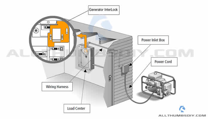
The interlock relay must not be used with the infinityevolution. Voltmeter wiring for 3 phase system. Electrical supervision of fire alarm devices. The hrv and furnace or fan coil blowers operate continuously when the hrv is energized. Detailed coloured12n trailer wiring diagram which is commonly used on uk and european trailers and caravans from western towing. An interlock is a feature that makes the state of two mechanisms or functions mutually dependent.
The afcs wiring diagram list the proper phase voltage and amp. Although the nbcc mandatesonlya manual shutdown of air moving fans in an air handlingsystem that is installed in a high building and that serves more than 2 storeys electrical designers also provide automatic interlocksfor such fun shutdown by a building fire alarm system. For example if we need that motor 1 should stop when motor 3 starts to run then we may use a normally close nc link of m3 in line 1.


