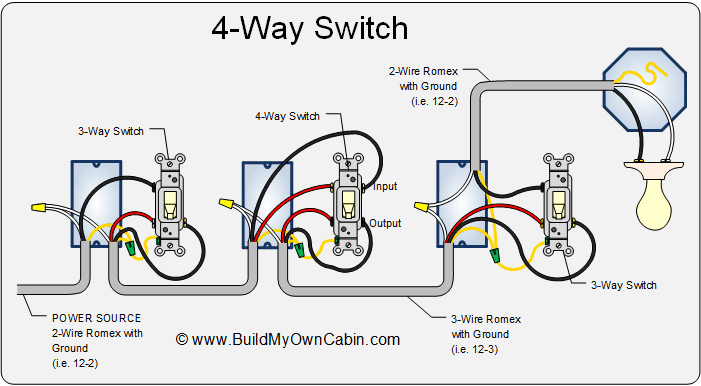
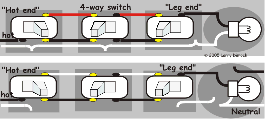
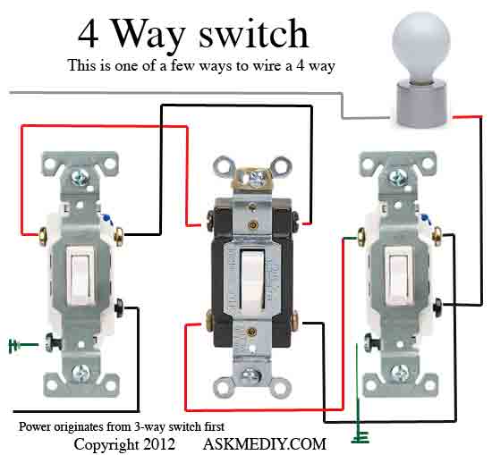
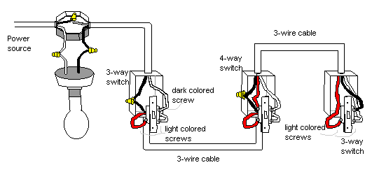
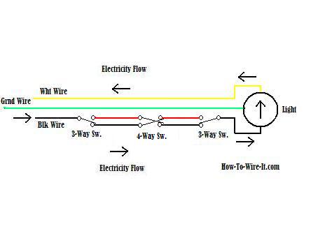
A 3 way switch wiring diagram is a simple drawing showing how to connect the wires to each of the four screws on the 3 way switch. In the diagrams below the first switch 3 way common terminal connects to line voltage.

Lutron 4 Way Switch Diagram Diagram Base Website Switch
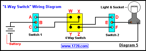
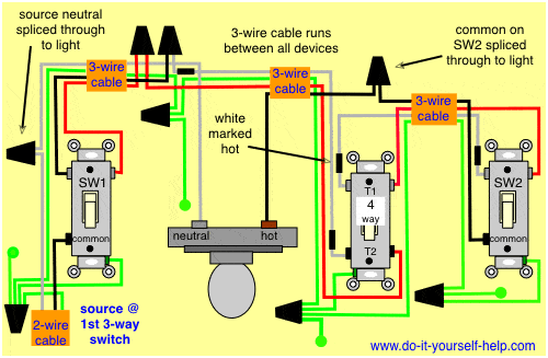
Four way switch circuit diagram. 4 way switch wiring 4 way switches provide switching from three or more locations. How to wire a 4 way switch. A 4 way switch wiring diagram is the clearest and easiest way to wire that pesky 4 way switch. Included are a 4 way dimmer switch diagram and an arrangement that can be used to control room lights from four different locations. Wiring a 4 way switch with light at. The black screw on a 3 way switch diagram is for the continuous hot wire that comes from the circuit.
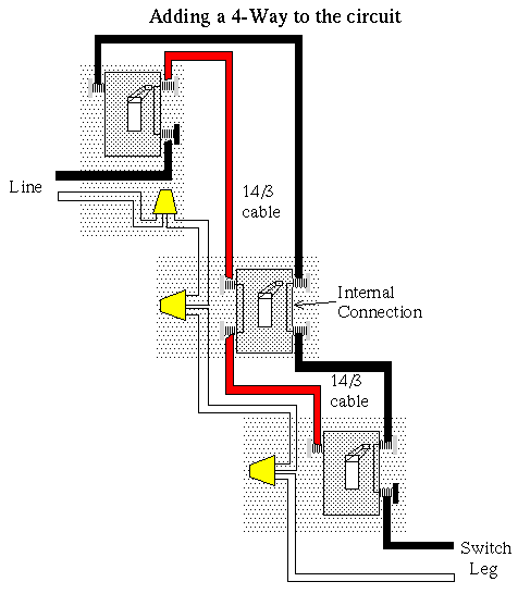
What is the black screw for on a 3 way switch diagram. As you will see most 4 way switch wiring is placed between the wiring of two 3 way switches therefore a 4way switch is installed with two 3way. The first switch 3 way travelers brass color connect to one pair of the second switch 4 way travelers black or brass color. The diagram below is based on the video you watched above. A four switch configuration will have two 3 way switches one on each end and two 4 way switches in the middle. I have a few of the most common ways in wiring a 4 way switch to help you with your basic home wiring projects.
If more than three switches are needed simply place more 4 way switches between the three way switches. For circuits that control lights from two locations only check the wiring diagrams at this link. Wiring a 4 way switch is simply adding a switch to an already existing 3 way switch circuit. Check here for 4 way switch troubleshooting and help with 3 ways switches here. First of all we need to go over a little basic terminology on switches. This allows you to control a load from other locations in addition to the 2 locations that a 3 way circuit provides.
