Before uninstalling the old thermostat take a picture of the wiring with your cell phone before removing the wires. Heat pump thermostat wiring chart diagram.

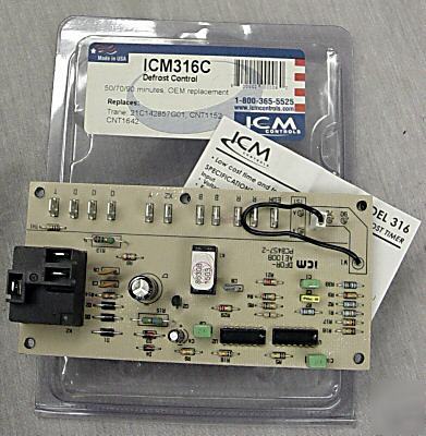
Icm Heat Pump Defrost Control For York Mccombs Supply Co
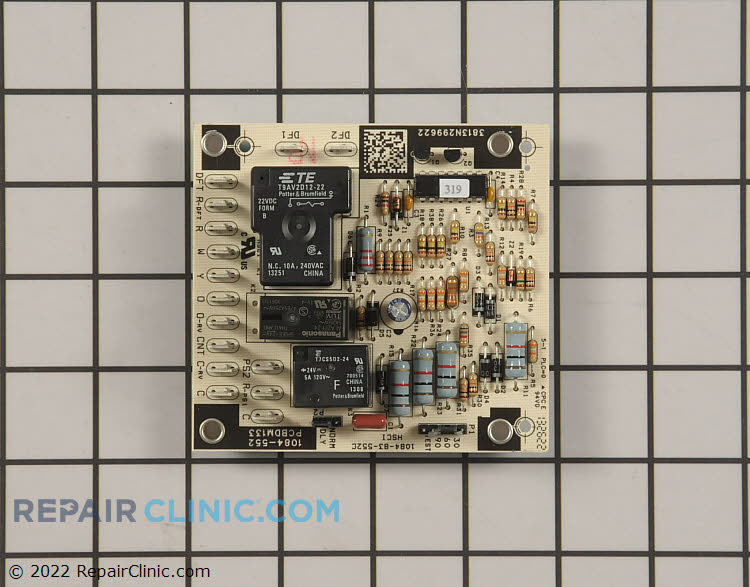
Heat pump defrost board wiring diagram. 3 permanent short will be ignored. Furnace control board wiring diagram elegant goodman heat pump. It corresponds to the chart below to explain the thermostat terminal functions. Heat pump 5060 hz. We have other articles here that will help you with thermostat wiringthese other articles help you with thermostat wiring colors and thermostat wiring diagramsin this article we will provide specific information for wiring a heat pump for control. York hvac wiring diagrams simple electronic circuits.
This way you have a reference. Heat pump operates in heating mode until the combination of outdoor ambient and outdoor coil temperatures initiate a defrost cycle. Opening of dft during defrost or interval period resets the interval to 0. Wiring diagrams index units produced after 033103. Defrost will terminate normally if dft is xlosed. Goodman defrost board wiring diagram collections of goodman defrost board wiring diagram for 133 wire center.
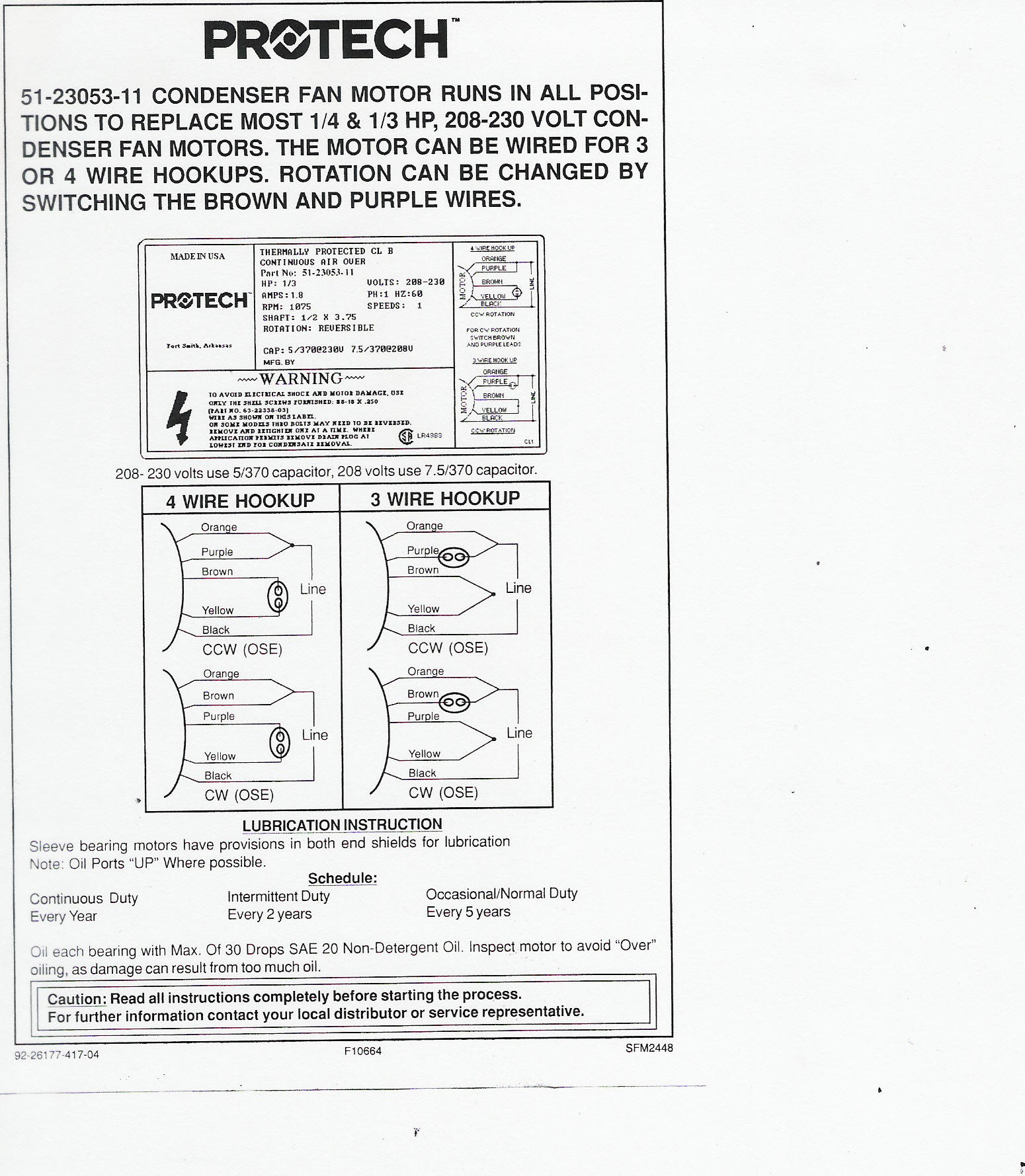
Wiring diagram split system heat pump new goodman gas pack wiring. Defrost will terminate in 30 sec. Goodman defrost board wiring diagram lennox wiring diagram for heat pump wire center u2022 rh ayseesra co heat pump wiring diagram heat pump wiring diagram goodman. 06 3 710235a replaces 7102350 710235z legend field wiring acto ry w ing. How to wire a heat pump for control there may be a time when you will want to change your old heat pump thermostat with a new heat pump thermostat. See installation instructions for wiring application and information concerning accessory heat kits and other options.
The basic heat pump wiring for a heat pump thermostat is illustrated here. Momentarily until the control is advanced to defrost cycle. The outdoor coil temperature must be at or below 32f before the. Electronic time temperature defrost controls dfc use a temperature sensing switch and an electronic timer circuit with on board relays for control of the outdoor fan the switch over valve the strip heat and the defrost relay edr during heat pump defrost cycles. Low voltage high voltage lls if equi ped blue orange orange. Factory power wiring field power wiring factory control wiring field control wiring conductor on circuit board component connection 14 inch quick connect terminals field splice junction auxr auxillary heat relay.
Two switch wiring fm cap defrost heat compressor heatcool 24 vac lar 132 1 las low ambient relay defrost r y bl bl bl g sec trans pri r bl bl r reset 24v transformer note 4 575460v bk t1 l1.


