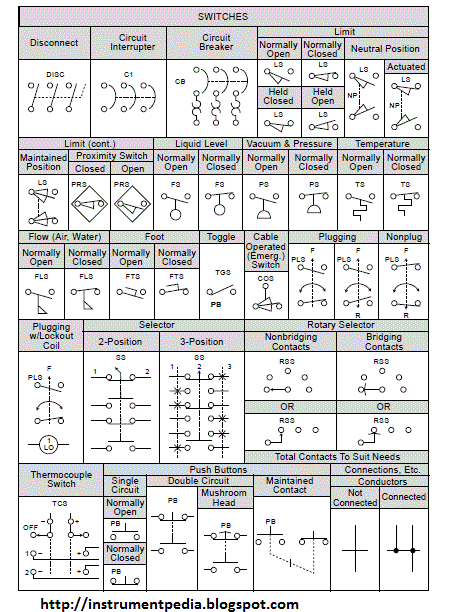
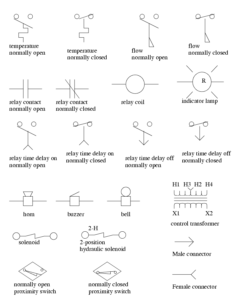
In this post we will discuss about what is a ladder diagram and how to draw a ladder diagram. As an introduction to ladder diagrams consider the simple wiring diagram for an electrical circuit in figure 1athe diagram shows the circuit for switching on or off an electric motor.

Reading Plc Wiring Diagram Symbols C3 Wiring Diagram
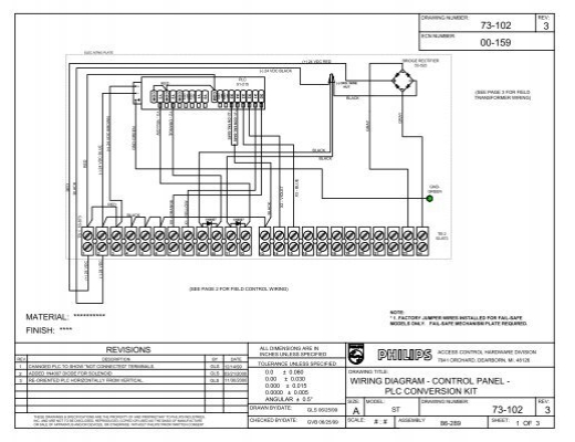
How to draw plc wiring diagram. To phrase it in a popular way you can say that there are 10 things you need to know in order to draw a wiring or power control circuit diagram quickly and effectively in pcschematic automation. Introduction to plc ladder diagrams. If you right click on a line you can change its line shape even after youve added it to the pageas well as add arrowheads if you need. Usually the wiring diagram refers to the electrical schematic or circuits diagram. But it does tend to become more complex. Start drawing lines by clicking on the draw lines tool in the smartpanel.
Easy to create wiring plans schematics circuit diagrams and more. How to place symbols. By default youll draw a straight line. This figure shows the e stop wired to cutoff power to all of the devices in the circuit including the plc. The first thing you need to know is how to place symbols in a diagram page in the software. If you want to change the type of line youre drawing select a line type from the line shape drop down.
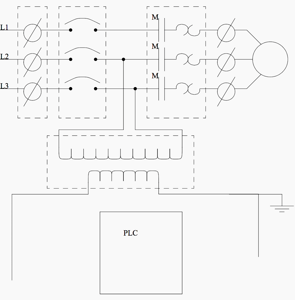
When including a plc in the ladder diagram still remains. Wiring diagram software with built in stencils for fast and efficient electrical wiring diagram design. This is a continuation of the previous article introduction to plc ladder programming in plc programming seriesplease go through an introduction to ladder programming before reading this post. Figure 5 below shows a schematic diagram for a plc based motor control system similar to the previous motor control example.
