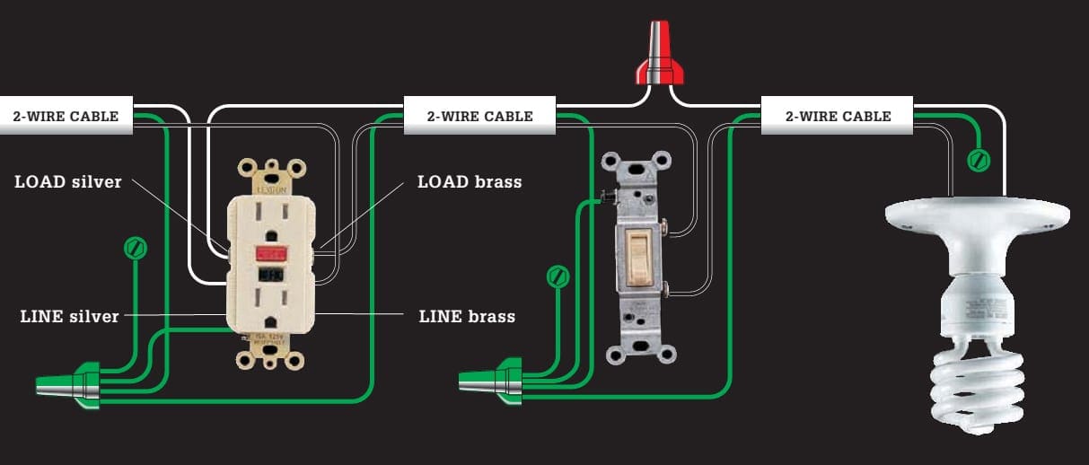
The power black wire connected on the load side of the gfci. Wiring diagram for a switched gfci combo outlet.

All About Wiring Diagrams
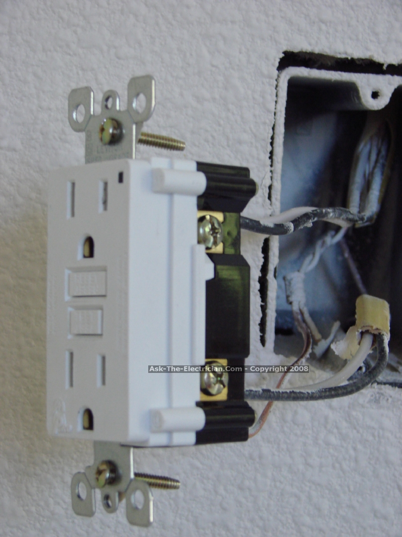
How to wire a gfci with switch diagram. The source hot wire is spliced with one of the switch wires and the other switch wire is connected to the hot line terminal on the device. I added another black wire on the bottom outlet same side. I have a gfci a light switch and a light. You can also learn about wiring gfci outlets in the following 7 steps. To wire a gfci circuit breaker see this link and wire a gfci switch combo at this link. There are three wires present one red wire attached to the left side upper terminal and two white wires attached to the right side terminals.
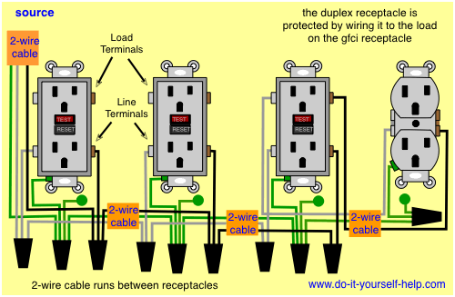
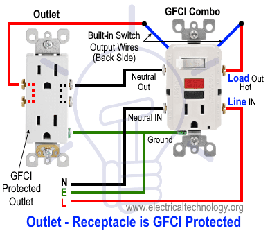
Gfci receptacle with a light fixture with an on off switch in likewise free electronic circuit diagram on floor plan light switch how do i wire a gfci switch combo home improvement stack exchange. Gfci combo switch and outlet wiring circuit diagrams and installation. Identifying the wiring for a new gfci outlet electrical question. It means all the connected loads to the load terminals of gfci are protected. Wiring for a switch and gfci receptacle in the same box is also shown. Wiring a gfci outlet with combo switch outlet receptacle light switch.
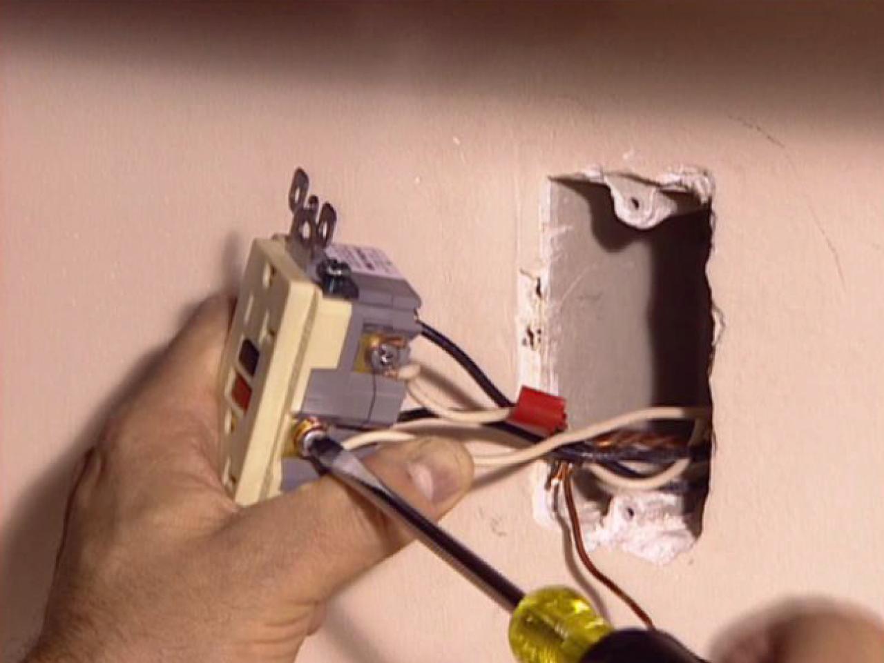
This diagram illustrates wiring a gfci receptacle and light switch in the same outlet box a common arrangement in a bathroom with limited space. Wiring diagram for gfci and light switch another picture. The above diagram shows the gfci wiring to multiple outlet as in white while the pictures are same. I added another black wire from the. Wiring a gfci receptacle is a little more complicated than hooking up a regular outlet but easily learned once explained. Wiring a gfci outlet and a light switch.
How to wire a gfci switch and light ask the electrician wiring a light switch diagram 1 wiring diagrams fully explained light switch wiring. My light has a green white and black wire. One side of the gfci connected to the ground neutral wire as shown white in the diagram and another side to the high potential hot wire shown as black in the diagram shows as in black color. How to wire gfci outlets. I am replacing an ungrounded 2nd generation duplex outlet with a gfci outlet. In this gfci outlet wiring and installation diagram the combo switch outlet spst single way switch and ordinary outlet is connected to the load side of gfci.
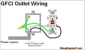
As discussed before gfci also known as ground fault circuit interrupter is a protection device against electric shock which detects the ground faults and leakage currents especially in outdoor and watery areas such as bathroom kitchen laundry etc. In this diagram the switch built into the combo device is wired to control the gfci outlet itself. The existing outlet is controlled by a switch. My power has a green black and white wire. The source neutral is connected the line neutral terminal. If you are replacing an existing gfci outlet with a new one we suggest that you read our page about replacing a gfci outlet.
I attached this black wire to the top left of the switch.


