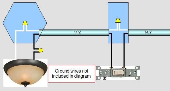
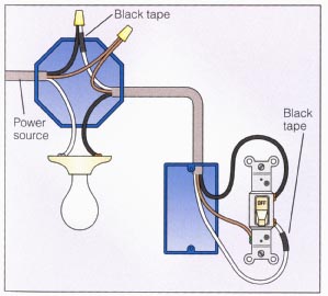
Next the incoming white neutral wire is attached to the light fixture as usual and the black wire from the switch is connected to the light fixture. This shows wiring a light switch when the power comes into the light outlet first.

Switch Loop Wiring Electrical Diy Chatroom Home
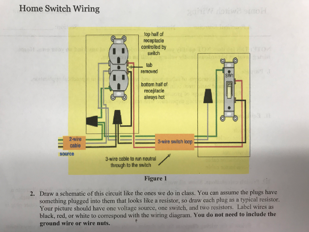
How to wire a switch loop diagram. This circuit is wired with a 2 wire cable running from the light to the switch location. When the electrical source originates at a light fixture and is controlled from a remote location a switch loop is used. Circuit electrical wiring enters the switch box. Pick the diagram that is most like the scenario you are in and see if you can wire your switch. How to wire a single switch. The hot source wire is removed from the receptacle and spliced to the red wire running to the switch.
The source is at the outlet and a switch loop is added to a new switch. Todays code says a neutral must also be present at every switch box even though it is not being used. Then we tie the black wire coming from that switch. Wiring a switch loop. This might seem intimidating but it does not have to be. Wrapping the wire clockwise when wiring a light switch ensures that the loop on the end of the wire will tend to close when the screw is tightened.
To make a switch loop connect the incoming hot black wire to the white neutral wire that runs to the switch. Switch wiring shows the power source power in starts at the switch box. The idea of a switch loop is that we take our incoming hot in the ceiling and tie it together with the white wire that goes down to the switch. Explanation of wiring diagram 1. This wiring diagram illustrates adding wiring for a light switch to control an existing wall outlet. Featuring wiring diagrams for single pole wall switches commonly used in the home.
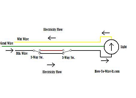
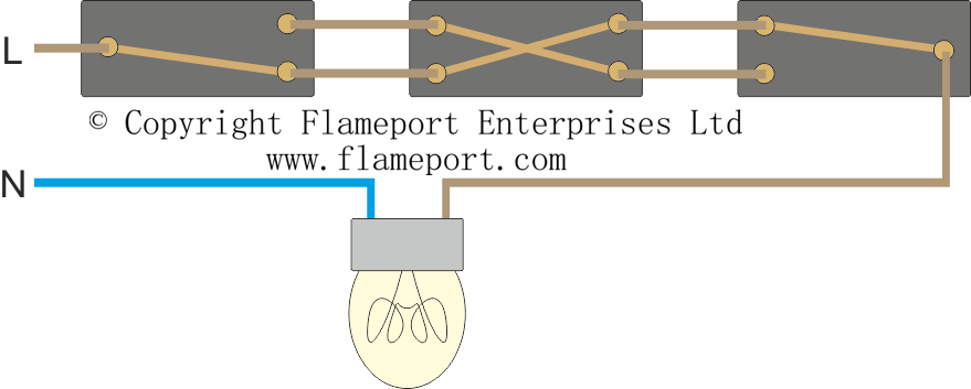
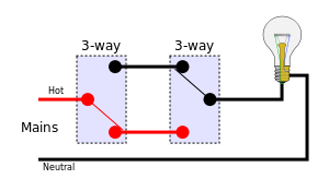
Technically the wire loop if you think about it is actually one wire with two different colors. It has no resistance in the branch circuit. If you put the loop over the screw in the counterclockwise direction tightening the screw will force the loop open and could create a loose connection. With these diagrams below it will take the guess work out of wiring. Take a closer look at a 3 way switch wiring diagram. Black wire power or hot wire white wire neutral bare copper ground.
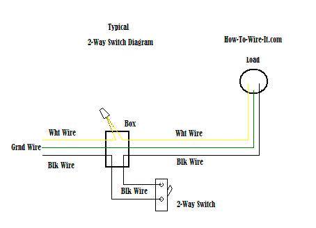
When wiring a 2 way switch circuit all we want to do is to control the black wire hot wire to turn on and off the load. Mark the white wire at each end with black tape or black paint to indicate it is hot. This simple diagram below will give you a better understanding of what this circuit is accomplishing. The old method of a 2 wire drop is explained along with the current code requirements of using a 3 wire cable. It only serves to make and break the circuit. The black wire from the switch connects to the hot on the receptacle.
