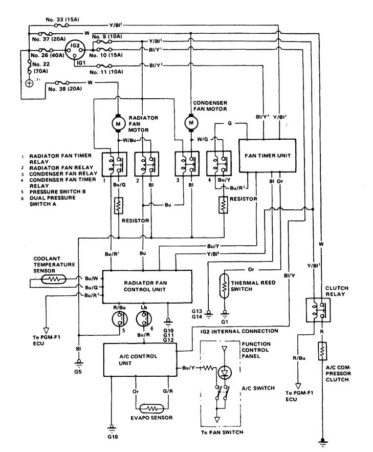
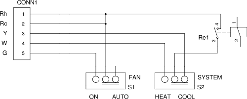
At the very least you should understand how to read circuit diagrams. An electric circuit is a closed loop with a continuous flow of electric current from the power supply to the load.
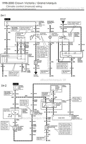
Mercury Grand Marquis Questions 1996 Mercury Grand Marquis
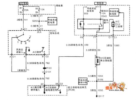
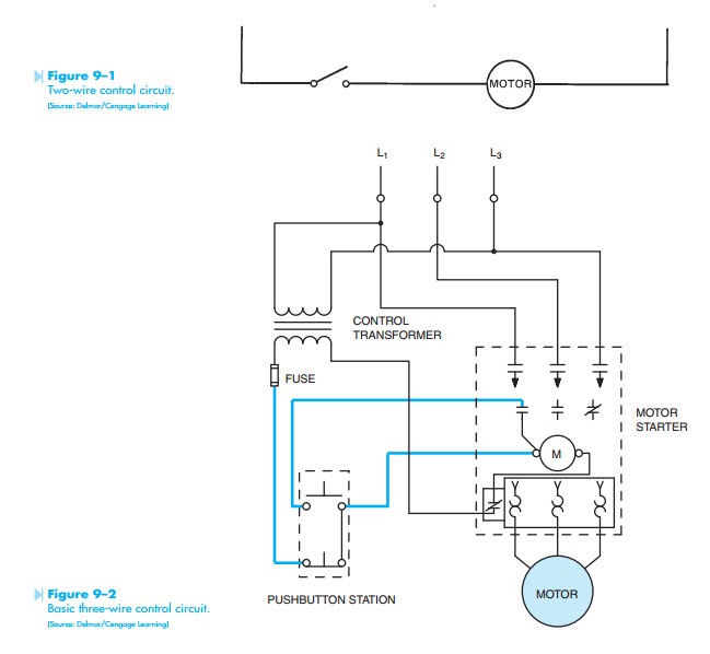
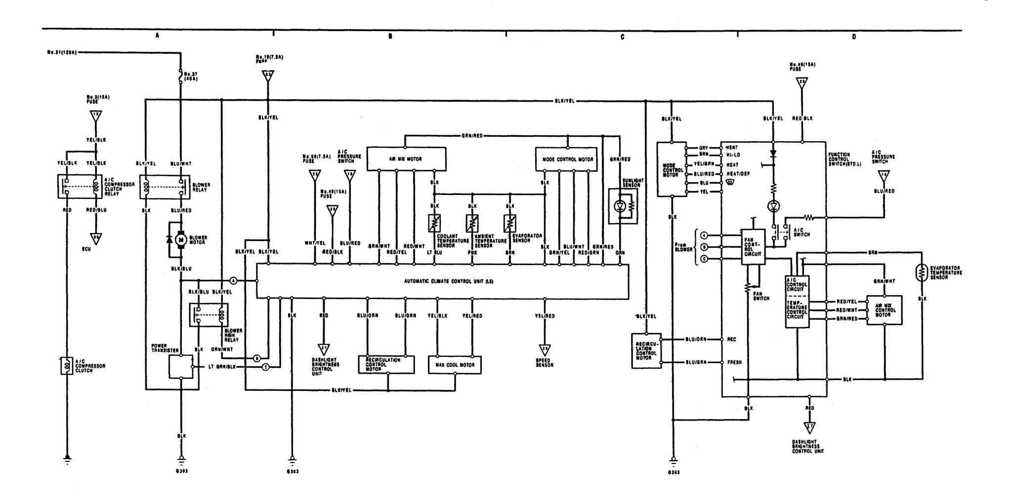
Hvac control circuit diagram. See more ideas about electrical diagram electrical circuit diagram electrical engineering. Figure 914 shows a start stop push button circuit. Control circuits for air conditioning and heating systems. Schematics are typically a for pros only affair. A very common form of latch circuit is the simple start stop relay circuit used for motor controls whereby a pair of momentary contact pushbutton switches control the operation of an electric motor. Furthermore this particular relay is controlled by the thermostat.
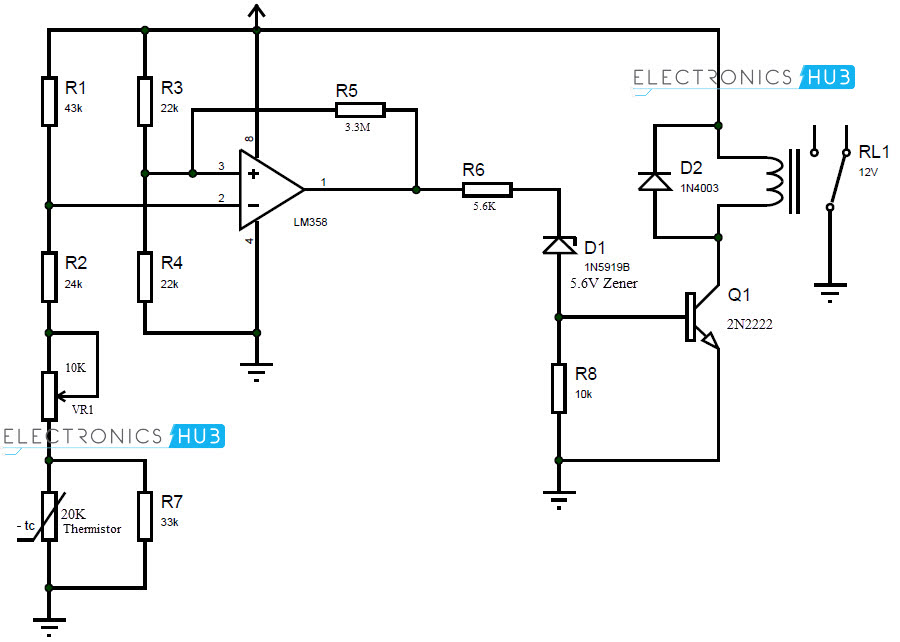
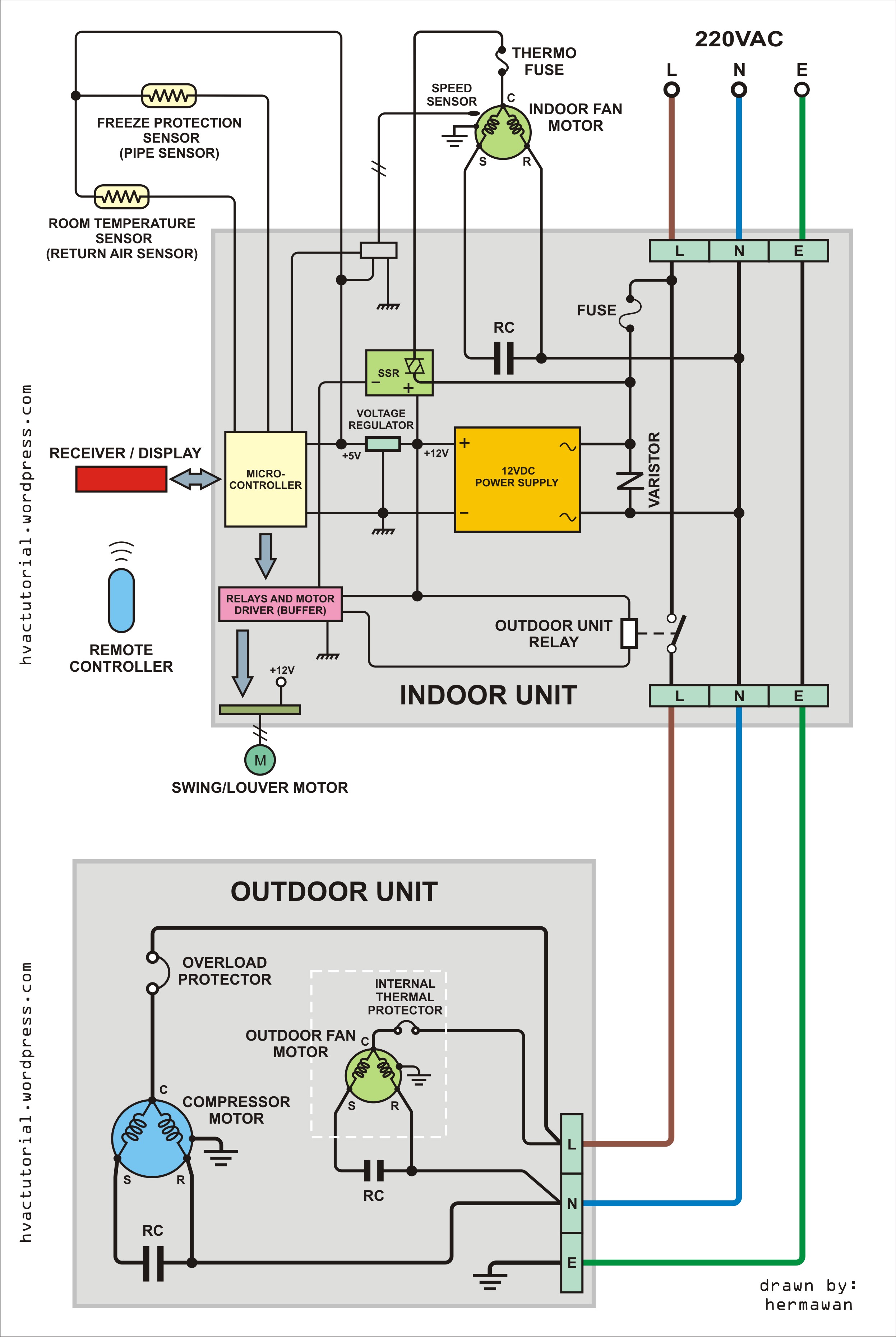
In this particular case i show a low voltage control circuit and a 3 phase higher voltage motor. Electric circuits like ac lighting circuit battery charging circuit energy meter switch circuit air conditioning circuit thermocouple circuit dc lighting circuit multimeter circuit current transformer. Read all the tech tips take the quizzes and find our handy. We walk through some of the basics and most common symbols associated with reading an air conditioner wiring schematic or diagram. Here are ten simple electric circuits commonly found around the home. Control systems for example usually are designed so that an individual circuit controls only.
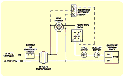
Many schematic diagrams show only the control circuit. The first circuit to be discussed is a basic control circuit used throughout industry. If you look at the individual circuits one at a time the overall diagram and machine functions become much easier to under stand. Power supplies may be indicated by solid lines or by dashed or dotted lines. This schematic shows both the control circuit and the motor circuit. Wiring diagram may appear very complex when viewed as a whole it can be simplified by breaking it down into smaller parts.
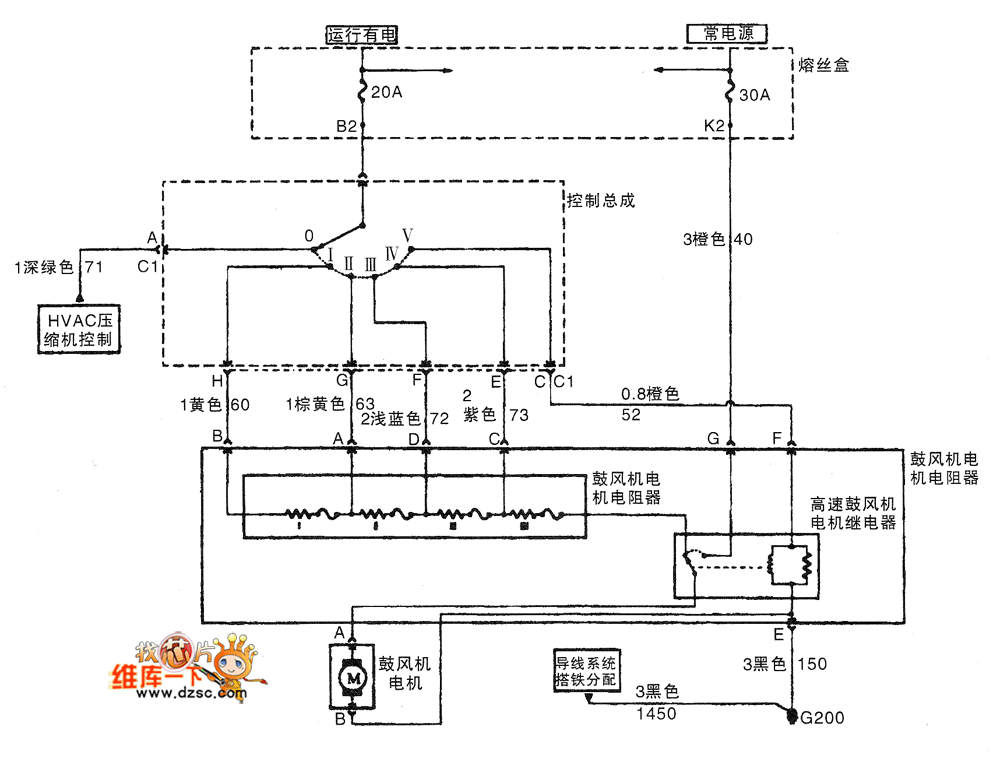
Schematic diagrams do not always show both control and motor connections. Thermostat wiring diagrams heat pumps are wired for hvac control far differently than air conditioning systems so make sure you know the difference and correctly identify the type of hvac system you have installed. However if you feel confident about your mechanical abilities and are contemplating a home hvac repair you certainly should give yourself a crash course in how to read them. Heres a briefing on some of those basics. Additionally before you decide to change your thermostat make sure you have the correct tools especially a screwdriver and wire pliers. The relay in the above control diagram controls a blower motor as shown.
Many different supply voltages are used in the hvacr industry ranging from 575 v three phase power supplies to 24 v control circuit voltages. The 24 volt neutral leg will run from the transformer. Feb 5 2020 explore elects agass board electrical diagram on pinterest. Then go to one side of a coil on the relay.

