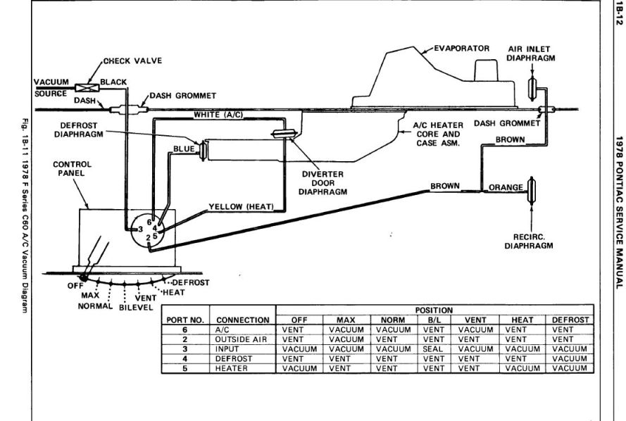
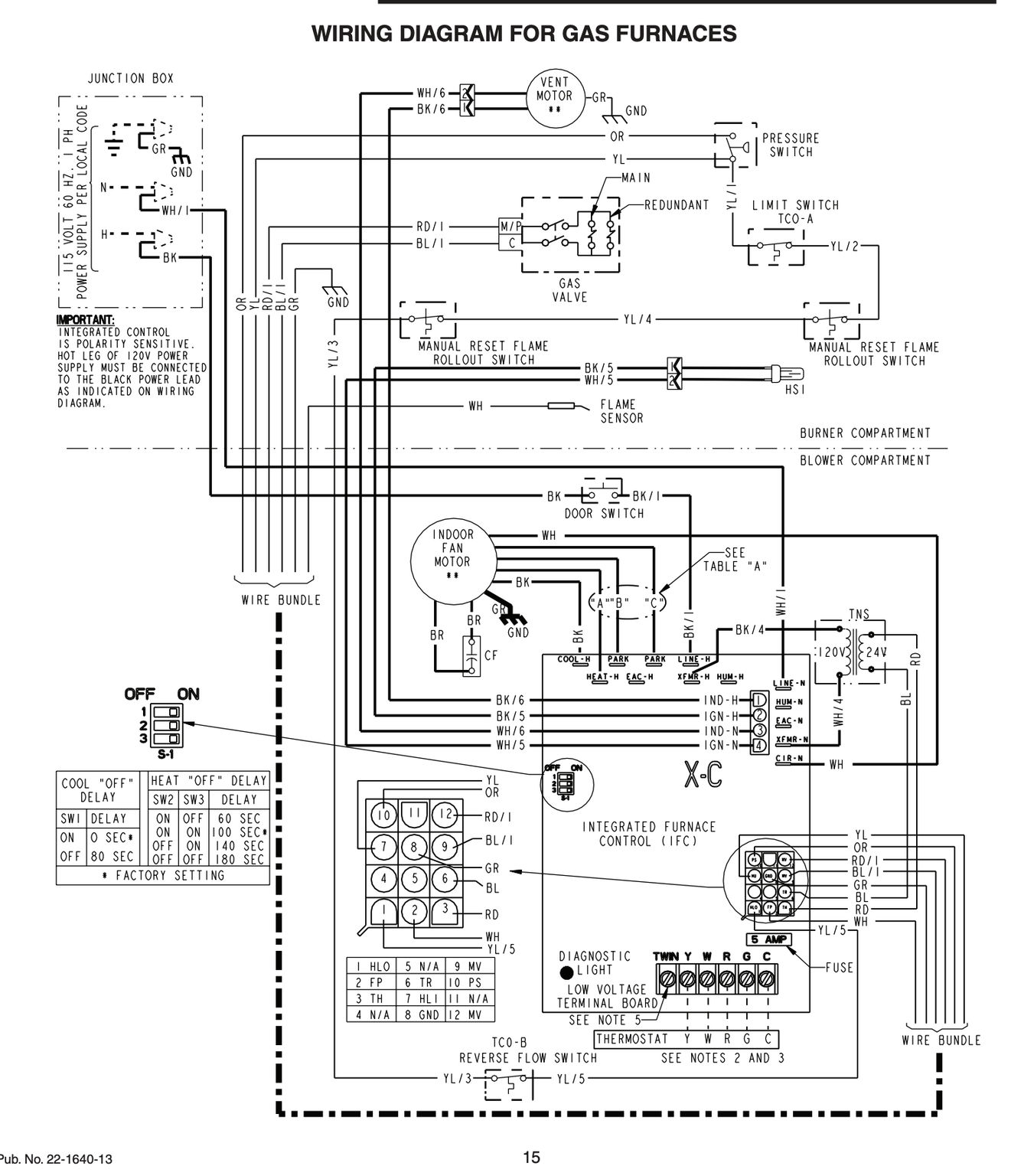
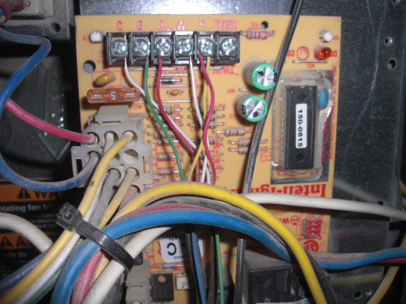
A wiring diagram is a simplified conventional photographic depiction of an electrical circuit. How to wire an air conditioner for control 5 wires the diagram below includes the typical control wiring for a conventional central air conditioning systemfurthermore it includes a thermostat a condenser and an air handler with a heat source.

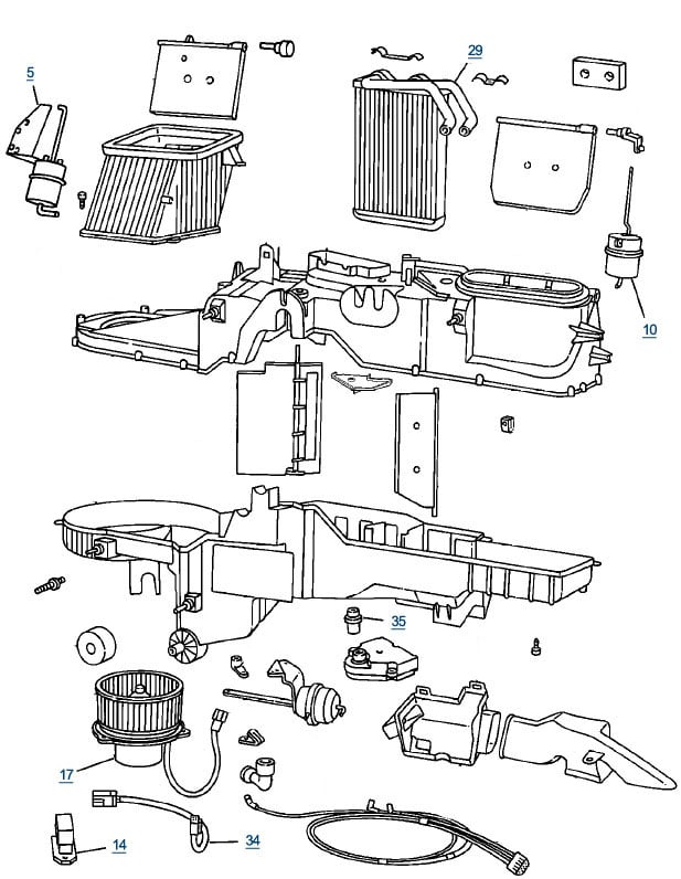
Components Symbols And Circuitry Of Air Conditioning Wiring
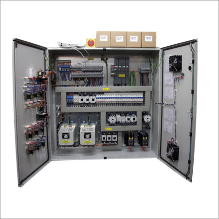
Hvac control panel wiring diagram. Interconnecting cable courses might be revealed about where specific receptacles or fixtures have to get on a typical circuit. Hvac control panel wiring diagram architectural wiring layouts reveal the approximate locations and affiliations of receptacles illumination and also permanent electrical services in a building. The components of the diagram will include a transformer low voltage source thermostat switch humidistat switch low voltage damper actuator load low voltage light load and a contactor with a low voltage coil load. Collection of hvac control panel wiring diagram. Read all the tech tips take the quizzes and find our handy. It reveals the components of the circuit as simplified shapes and also the power and also signal connections between the gadgets.
Generic nomenclature will suffice since we are demonstrating the making of a wiring diagram. We walk through some of the basics and most common symbols associated with reading an air conditioner wiring schematic or diagram. Moreover the heat source for a basic ac system can include heat strips for electric heat or even a hot water coil inside the. Additionally before you decide to change your thermostat make sure you have the correct tools especially a screwdriver and wire pliers. Thermostat wiring diagrams heat pumps are wired for hvac control far differently than air conditioning systems so make sure you know the difference and correctly identify the type of hvac system you have installed.
