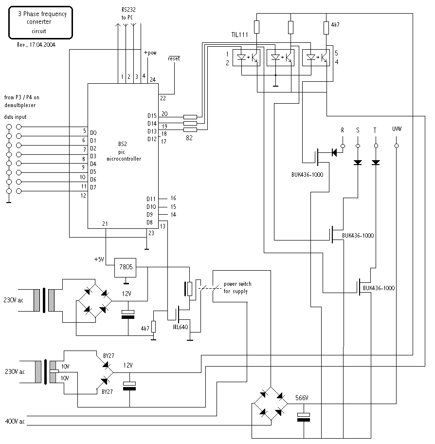
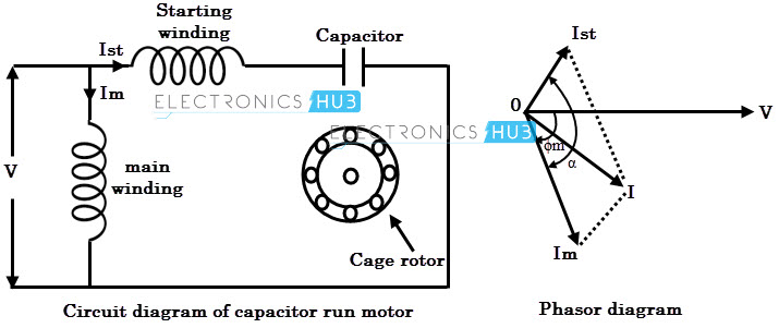
Capacitor start capacitor run induction motors are single phase induction motors that have a capacitor in the start winding and in the run winding as shown in figure 12 and 13 wiring diagram. Single phase motor wiring diagram with capacitor baldor single phase motor wiring diagram with capacitor single phase fan motor wiring diagram with capacitor single phase motor connection diagram with capacitor every electrical arrangement is made up of various unique pieces.
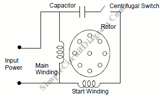
Capacitor Start Ac Induction Motor Simple Circuit Diagram
Induction motor circuit diagram. Er 1 2 4 5 ocdevgl gl gamma. To build an ac permanent capacitor split phase induction motor. The single phase induction motor circuit is given by double revolving field theory which states that a stationary pulsating magnetic field might be resolved into two rotating fields both having equal magnitude but opposite in direction. Induction motor equivalent circuit from the preceding we can utilise the equivalent circuit of a transformer to model an induction motor. So the net torque induced is zero at standstill. This type of motor is designed to provide strong starting torque and strong running for applications such as large water pumps.
Learn how a capacitor start induction run motor is capable of producing twice as much torque of a split phase motor. To illustrate the simplicity of the ac induction motor. Pgs ocdedv gamma series d 1417 diags. Wiring diagrams standard motors m 3ø wiring diagrams 1ø wiring diagrams m 3 m 3 high speed delta connection low speed star connection w2 or white w2 or white. Three phase motor power control wiring diagrams three phase motor connection schematic power and control wiring installation diagrams. There is a difference between single phase and three phase equivalent circuits.
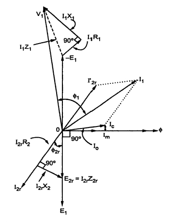
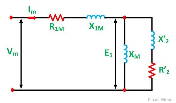
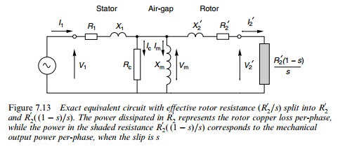
In the equivalent circuit r 1 represents the resistance of the stator winding and x 1 the stator leakage reactance flux that does not link with the air gap and rotor. The stator circuit model of an induction motor consists of a stator phase winding resistance r 1 stator phase winding leakage reactance x 1 as shown in the circuit diagram below. Lessons in electric circuits volume 2 chapter 13. Star delta y δ 3 phase motor starting method by automatic star delta starter with timer. Some standard frame induction motor diagrams have been included for ease of presentation. Each component ought to be placed and linked to different parts in particular manner.
Repulsion start induction electric motor reversible a repulsion start induction motor is a single phase motor having the same windings as a repulsion motor but at a predetermined speed the rotor winding is short circuited or otherwise connected to give the equivalent of a squirrel cage winding. Click here to view a capacitor start motor circuit diagram for starting a single phase motor. Wondering how a capacitor can be used to start a single phase motor. Also read about the speed torque characteristics of these motors along with its different types. The no load current i 0 is simulated by a pure inductive reactor x 0 taking the magnetizing component i µ and a noninductive resistor r 0 carrying the core loss. Ac motors single phase induction motorspermanent split capacitor motor.
