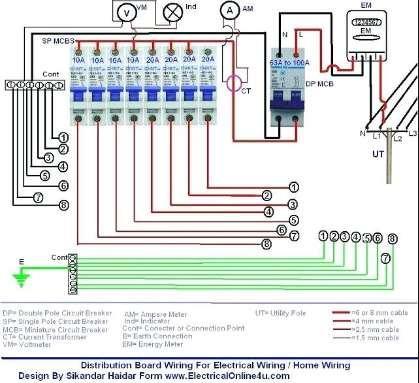
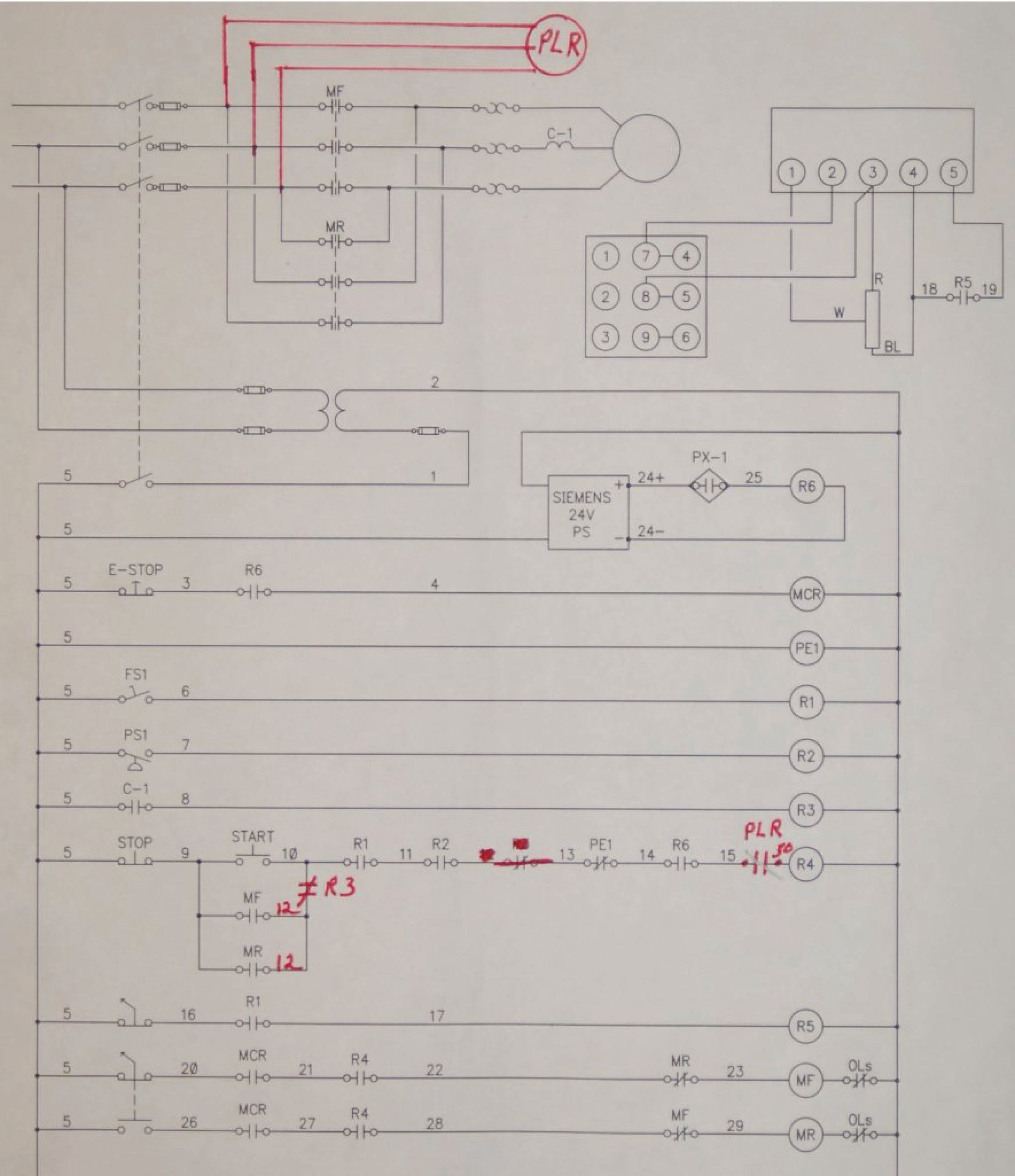
From an electrical standpoint industrial machine equipment and tools from drill presses to multi motored automatic machines. Electrician circuit drawings and wiring diagrams youth explore trades skills 3 pictorial diagram.
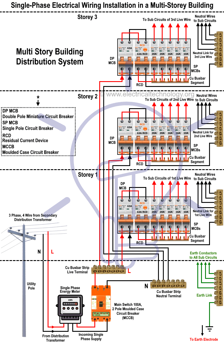
440 Volts Wiring Diagrams Camrysde 9 Mareikekirsch De
Industrial electrical wiring diagram. Because every type of machine has unique requirements for wiring methods operator safety depends on your understanding the differences between rules in the nec and methods outlined in nfpa 79every type of machine has unique requirements when it comes to operator safety. The electrical design for each machine must include at least the following components. Basics 10 480 v pump schematic. The wiring diagram for connecting thee phase motor to the supply along with control wiring is shown in figure below. Basics 13 valve limit switch legend. Transformers to step down ac supply voltages to lower levels.
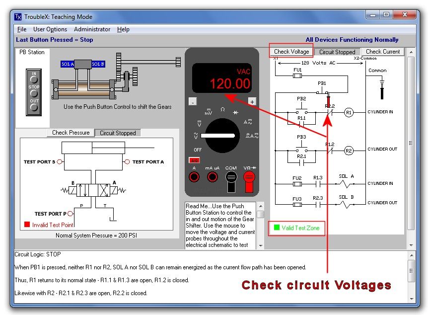
Basics 7 416 kv 3 line diagram. Here is a standard wiring symbol legend showing a detailed documentation of common symbols that are used in wiring diagrams home wiring plans and electrical wiring blueprints. A diagram that uses lines to represent the wires and symbols to represent components. This is a start stop push button control schematic which includes contactor m overload relay control transformer and push buttons. Many people can read and understand schematics known as label or line diagrams. In an industrial setting a plc is not simply plugged into a wall socket.
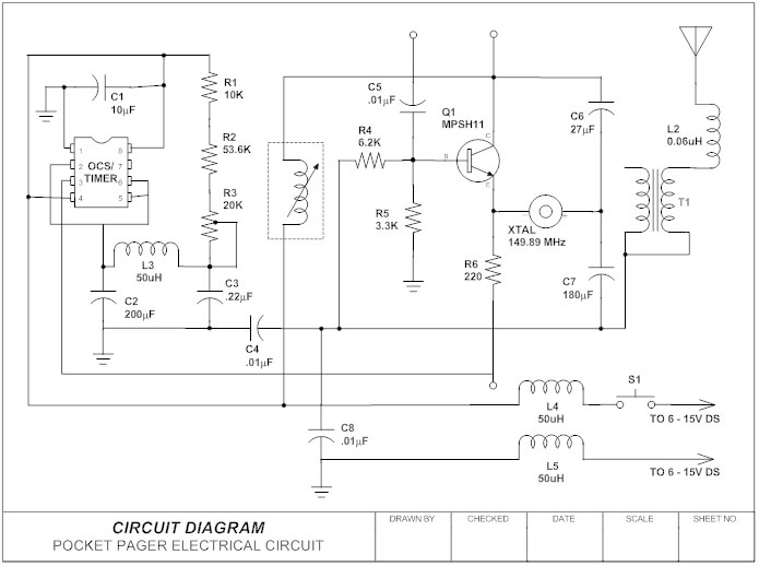
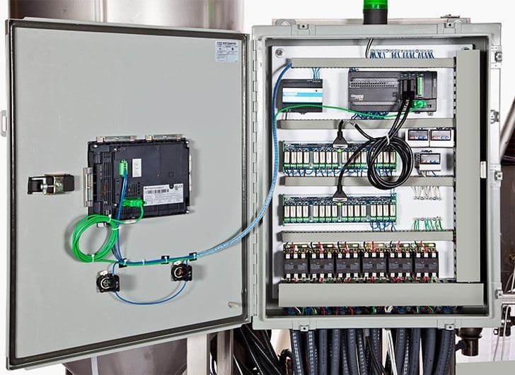
A diagram that represents the elements of a system using abstract graphic drawings or realistic pictures. Electrical wiring diagrams of a plc panel. It wasnt so easy to create electrical symbols and electrical diagram as it is now with electrical diagram symbols offered by the libraries of electrical engineering solution from the industrial engineering area at the conceptdraw solution park. Figure 7 shows the system used for large industrial plants where most of the load consists of motors. It shows the elements of the circuit as simplified shapes and also the power as well as signal links in between the gadgets. The contactor contains large load contacts that are intend to handle large amount of current.
This type of diagram is like taking a photograph of the parts and wires all connected up. Wiring diagrams use simplified symbols to represent switches lights outlets etc. How to create electrical diagram. This solution provides 26 libraries which contain 926. Transformers are used to get 120 volt single phase circuits. It is a 480 volt delta three phase system.
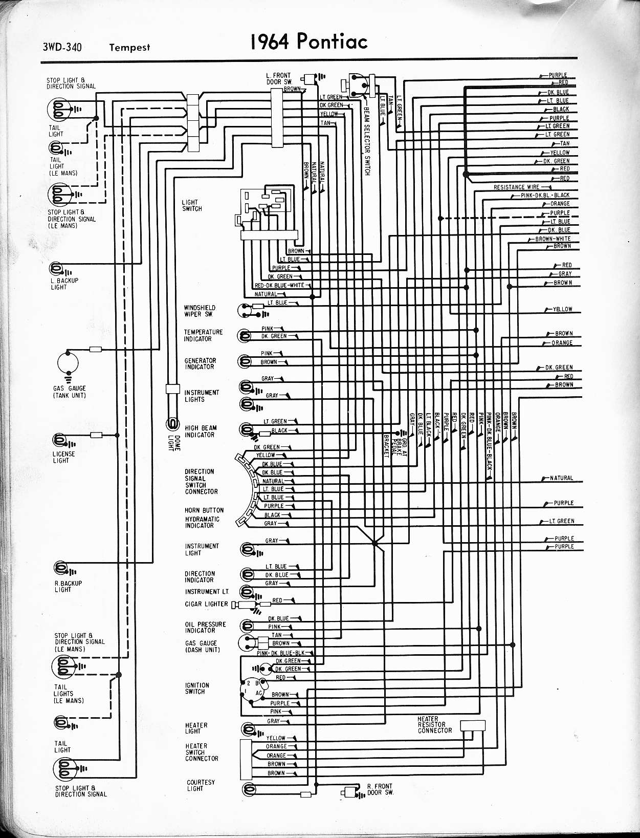
Basics 11 mov schematic with block included basics 12 12 208 vac panel diagram. A wiring diagram is a streamlined standard pictorial depiction of an electric circuit. Basics 14 aov schematic with block included basics 15 wiring or connection. Collection of john deere wiring diagram download. Figure 6 is a diagram for a 480276 volt three phase four wire system. Wiring diagrams help technicians to see how the controls are wired to the system.
All you need is a powerful software. This system serves hotels shopping centers etc. Basics 8 aov elementary block diagram. Basics 9 416 kv pump schematic.

