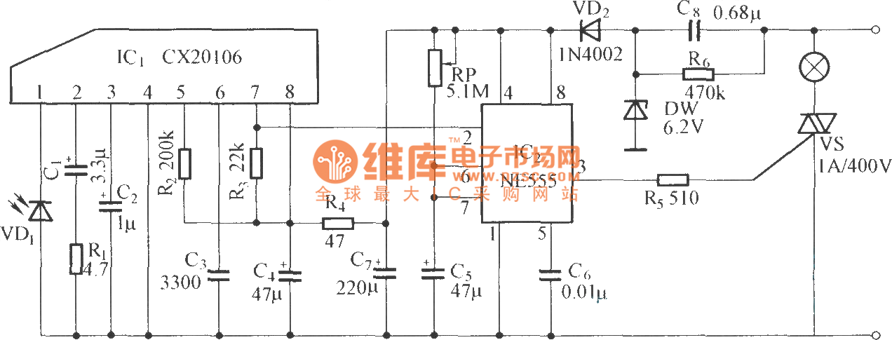
This current is given to the inverting input of 3130 ic which will get triggered by this current and give amplified output. In the receiver section there are 3 photodiodes which will detect the infrared signals from the receiver and produce leakage current to the capacitor c1.

Cl 5846 Arduino Ir Remote Control Additionally Rf Remote
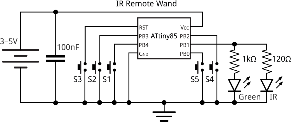
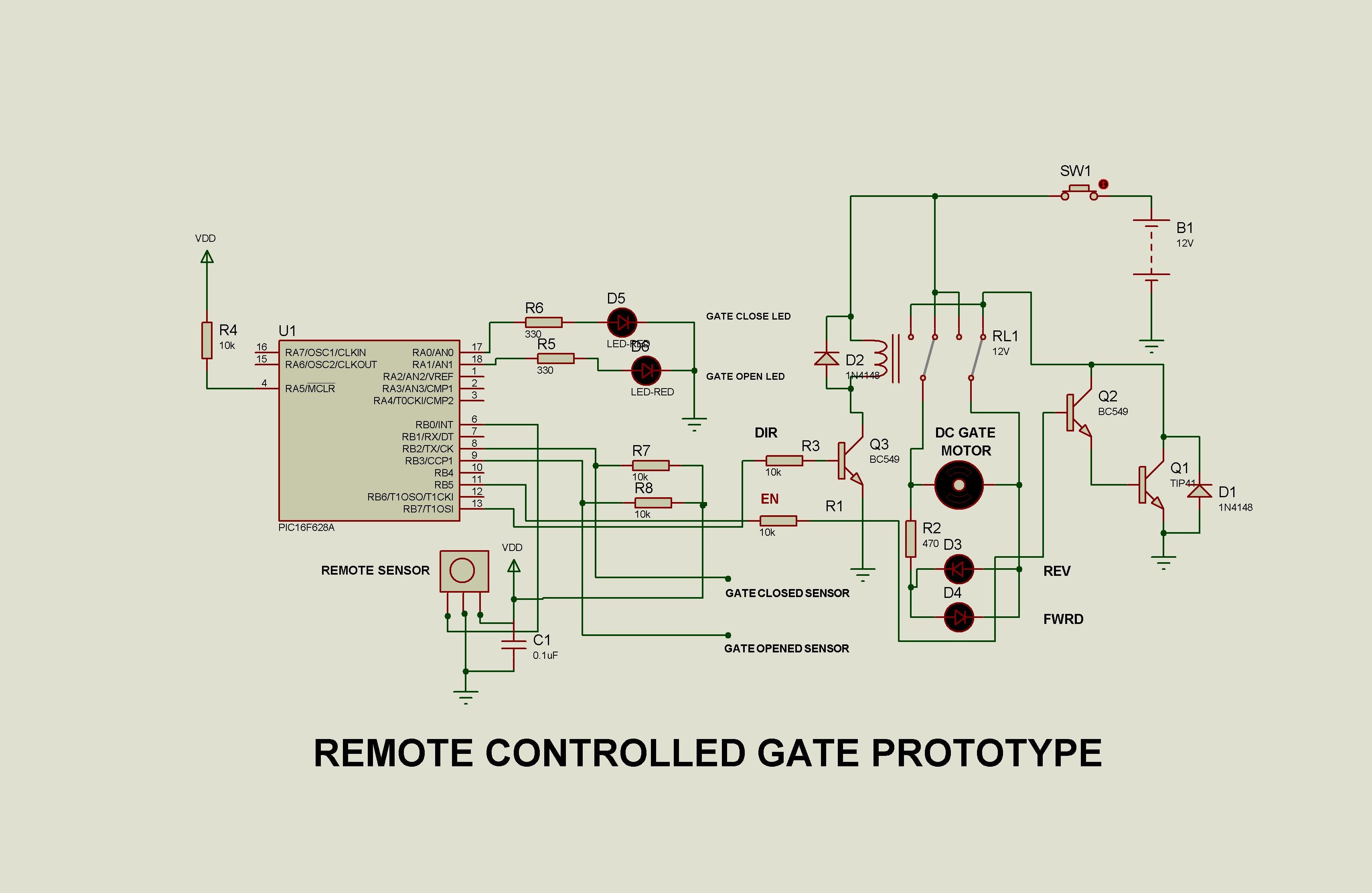
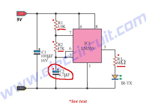
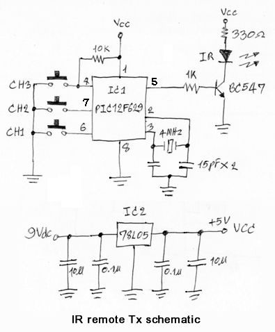
Ir remote control circuit diagram. Here the circuit of a single channel infrared remote controller which can be used to control home appliances and devices. Lm7805 voltage regulator is also added in to the circuit for providing 5 volt voltage supply to the circuit and a 9 volt battery is used for powering the circuit. Diy remote control snake by techgenie in remote control. This circuit can easily control your home appliances. We uses normal switch in our daily life and after a long time used to these swithing system we can no more interested in that. The working of the design is self explanatory.
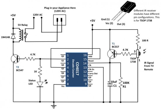
Ir remote control circuit diagram. When the remote control handsets button is pressed and pointed towards the photodiode of the circuit the photodiode begins conducting and allows a few mv to pass through it. We have used ic 4017 to convert it into a push on push off switch. Circuit diagram and explanation. Circuit diagram of infrared remote control switch. By admin published march 28 2017 updated august 21 2018.
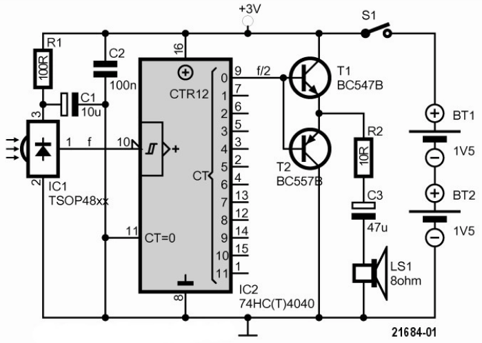
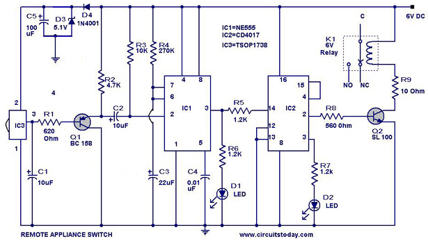
Tv generally consist tsop1738 as the ir receiver which senses modulated ir pulses and convert them into electrical signal. As shown in the above ir remote control tester circuit we have connected a buzzer and a yellow led for indication. This is a good solution for a unique and so interesting idea to wireless switching system to control the home appliance. Any type of remote can be used to control this circuit like dvd tv cd player and so on. Customizable ir remote replacement no android programming required by drmpf in remote control. Receiver circuit is connected to ac appliance via relay so that we can control the light remotely.
In this write up we discuss a couple of these simple infrared remote control circuits designed for controlling any given electrical appliance through an ordinary or tv remote control unit. Ir remote control circuit for controlling home appliances can be easily made using decade counter ic cd4017 and any tsop can be used infrared receiver. Ir transmitter and receiver are used to control any device wirelessly means remotelytv remote and tv are the best example of ir transmitter and receiver. This is the very simple circuit diagram of ir remote control switch. A simple remote tester circuit using just 2 transistors can be seen in the above figure. The ir remote controller consists of a.
The proposed infrared or ir remote control circuit can be used to operate an appliance onoff through any standard tv remote control handset. In this remote controlled switch circuit we are using tv remote to onoff the ac light by pressing any button of remote and using the tsop1738 at receiver end.

