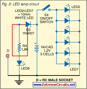
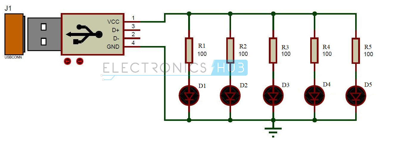
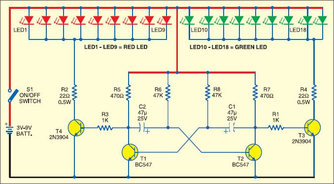
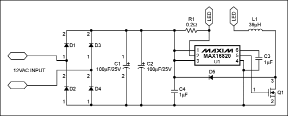
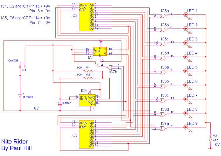
Symbol definitions are as follows. The circuit diagram for leds in parallel connection is shown in the following image.

How To Install Led Lights On Your Motorcycle
Led lighting circuit diagram. The circuit must provide sufficient current to light the led at the required brightness but must limit the current to prevent damaging the led. Components required for leds in parallel. Simple led light emitting diode circuit diagram. Hence the name light emitting diode led. The led symbol is the standard symbol for a diode with the addition of two small arrows denoting emission of light. In electronics an led circuit or led driver is an electrical circuit used to power a light emitting diode led.
The circuit diagram of a blinking led that can be operated from the mains supply is shown here. Running a series circuit helps to provide the same amount of current to each led. The basic principle behind the 230v led driver circuit is transformer less power supply. The final circuit in the simple led circuits tutorial is leds in parallel. Circuit diagram of leds in parallel. In this circuit we will try to connect three 5mm white leds in parallel and light them up using a 12v supply.
The requirements of a lighting application often dictate what type of circuit can be used but if given the choice the most efficient way to run high power leds is using a series circuit with a constant current led driver. The working of this circuit is as follows. Diy motion sensor light using led bulb and pir sensor. The circuit diagrams or schematics that follow are drawn using industry standard electronic symbols for each component. These capacitors are connected line to line and are designed for high voltage ac circuits. The main component is the x rated ac capacitor which can reduce the supply current to a suitable amount.


