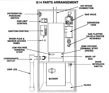
If not the arrangement will not function as it should be. 1 heat which uses the compressorheat pump system to heat the house and 2 e heat mode which bypasses the compressor and uses a gas furnace in the attic and blows through the same duct work as the heat pump system.
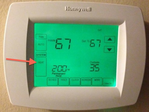
How Not To Use Your Heat Pump Thermostat
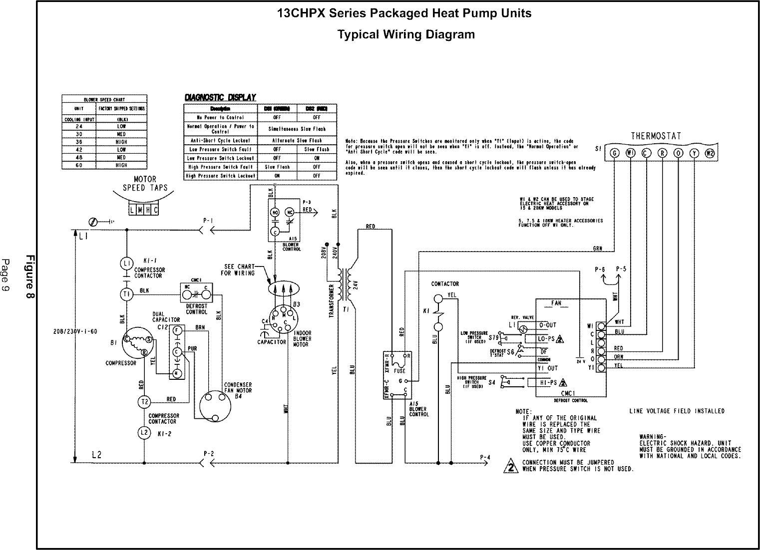
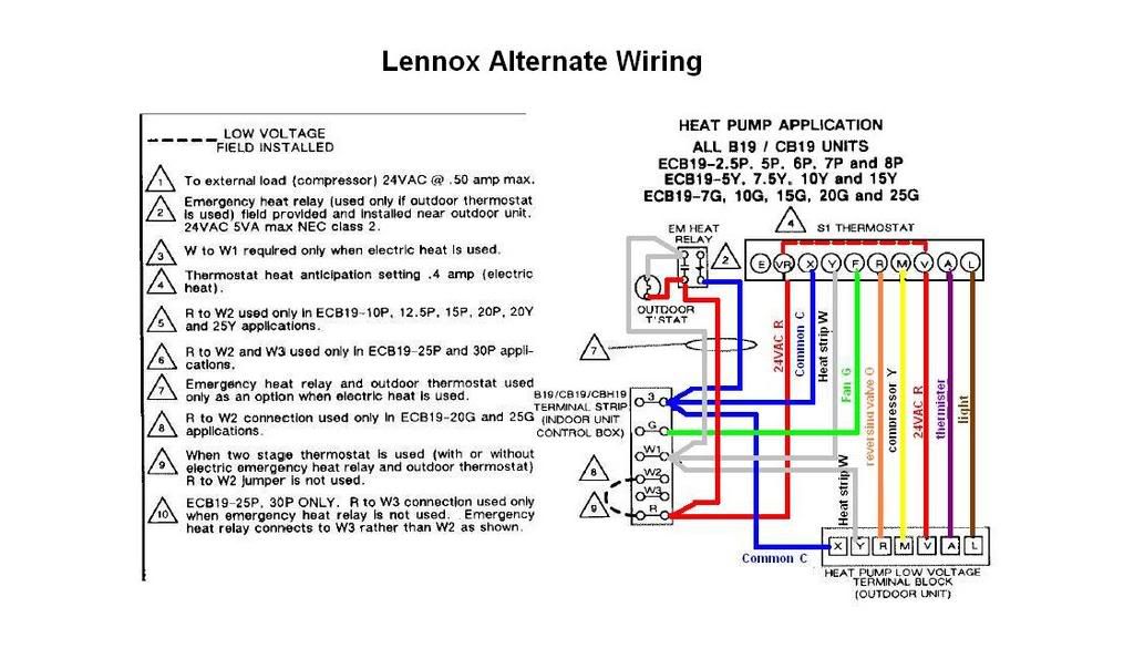
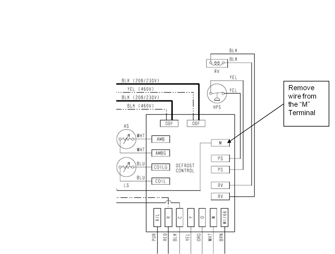
Lennox wiring diagram for heat pump. It shows the components of the circuit as simplified forms and also the power and also signal connections between the devices. Each part should be placed and connected with different parts in particular way. 14hpx018 14hpx024 14hpx030 14hpx036 14hpx042 14hpx048 14hpx060. Collection of lennox wiring diagram. Installation instructions dave lennox signature collection xp17 system heat pumps 50658601 0611 supersedes 0511 table of contents. Heat pump thermostat wiring chart diagram hvac the following graphics are meant as a guide only.
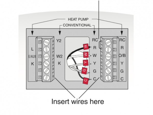
As shown in the diagram you will need to power up the thermostat and the 24v ac power is connected to the r and c terminals. 15 to 5 ton 14hpx series residential split system heat pump unit. The heat pump functions as both a heating and cooling system reducing gas fuel consumption. See the icomfort touch thermostat quick start guide for communicating and partial communicating field wiring connections. The color of wire r is usually red and c is black. 14hpx heat pump pdf manual download.
Always follow manufacturers instructions for both the thermostat and the hvac system. These two connections will ensure that there is power to the thermostat that you are operating. Heat pump thermostat wiring a typical wire color and terminal diagram. Additional articles on this site concerning thermostats and wiring can help you solve your problem or correctly wire a new thermostat. Field wiring examples for nonicomfort applications begin on page 25. Heat pump thermostat wiring diagram carrier heat pump thermostat wiring diagram coleman heat pump thermostat wiring diagram goodman heat pump thermostat wiring diagram every electric arrangement is composed of various different pieces.
On extra cold days the gas furnace becomes the primary heat source ensuring maximum comfort is maintained. C is known as the common terminal. View and download lennox 14hpx unit information online. A wiring diagram is a streamlined traditional photographic depiction of an electrical circuit. When you combine a compatible lennox heat pump with an efficient lennox furnace you can create an energy saving dual fuel system. Find best value and selection for your lennox outdoor heat pump remote sensor for dsl thermostat lx odt 37k09 new search on ebay.


