The impeller moves water called drive water from the well through a narrow orifice or jet mounted in the. Single phase water pump motor wiring diagram how to connect submersible pump wires wiring diagram for 220 volt submersible pump 3 phase submersible pump starter wiring diagram.

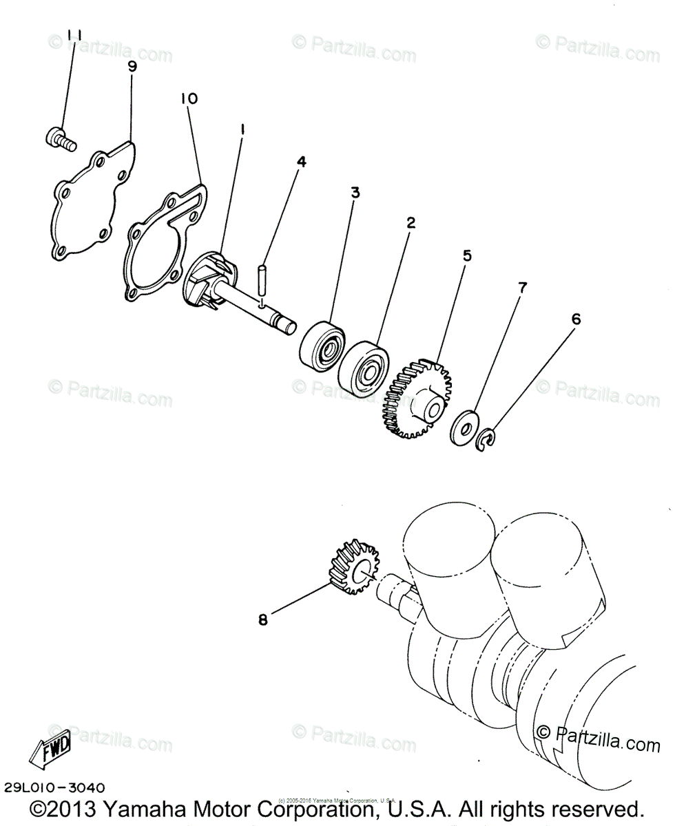
Dynaflo Series Pump Parts Primo Pumps Amp Fire Equipment
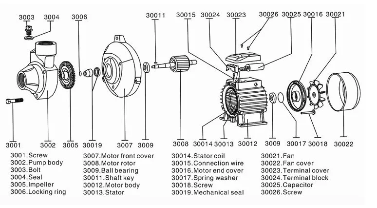
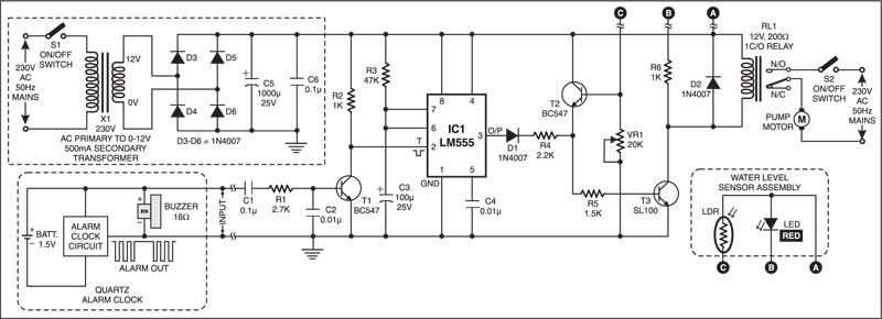
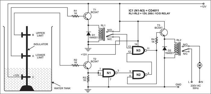
Water pump motor diagram. Over load relay 4. Contactor 220 v 3. Well pump water pump controls. Ultimately using some simple electrical tests the homeowner traced the water pump problems to a nicked well pump wiring circuit wire. The pump is powered by an electric motor that drives an impeller or centrifugal pump. Water pump motor schematic diagram scj tech vlog.
Single phase wiring diagrams single phase wiring diagram for 05hp pumps with governor switch single phase wiring diagram with governor switch single phase wiring diagram without governor switch three phase wiring diagrams three phase 208v wiring diagram three phase 230v wiring diagram three phase 460v wiring diagram three phase 575v wiring diagram kb pump wiring diagrams kb pump 230v wiring. Cb circuit breaker 2. This article describes and identifies the switches controls and safety devices used on water tanks and water pumps such as the pump pressure control switch pump motor relays water tank relief valve water tank pressure gauge water tank air volume control and water tank air valve. Well pump wiring diagnosis repair. This article describes troubleshooting a submersible well pump that was causing tripped circuit breakers and that pumped water only at a slow reduced rate and pressure.


