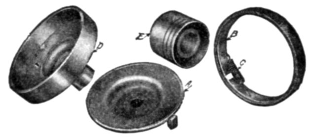
Learn how a capacitor start induction run motor is capable of producing twice as much torque of a split phase motor. Singlephaseinductionmotor repaircentrifugalswitch or motor clutch repair electricalchannel clutch motor working clutch motor wiring diagram juki sewing machine motor price sewing machine.

Motor Ki Clutch Plate Ko Kaise Set Kare By Ravi Electrician
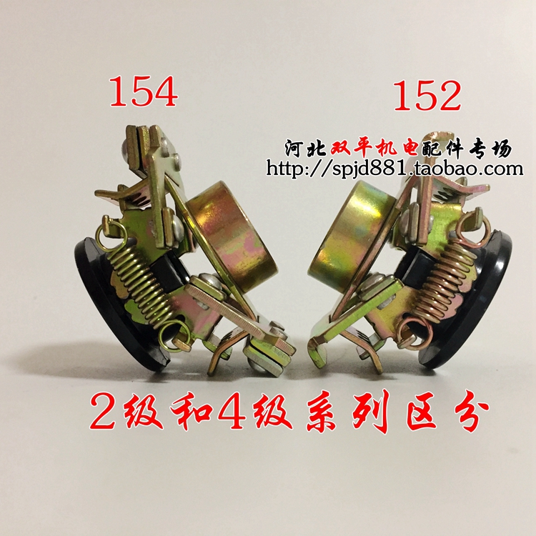
Single phase motor clutch plate connection. R1 coil r2 similarly for b phase and y phase. From this motor nameplatewe can see it have 2 connection and 2 voltage valueif our power supply voltage is 415 vac for 3 phasewe need to setting the motor terminal in star connection. A single phase sets up an oscillating magnetic field that goes back and forth rather than a rotating magnetic field see bottom figure. How to change single phase motor clutch plate सगल फज मटर क कलच पलट बदलन सख duration. A three phase motor may be run from a single phase power source. Yes it is possible to connect 3 phase motors in star as well as delta connection if you have winding ends noted well ie r phase.
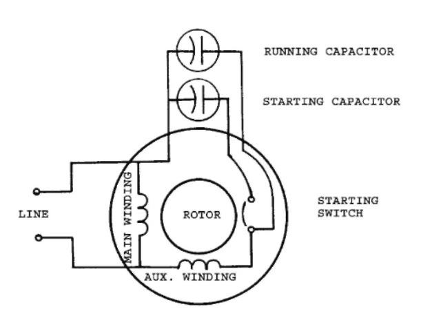
For all other single phase wiring diagrams refer to the manufacturers data on the motor. Single coil of a single phase motor. The main winding of a single phase motor is designated by t1 t2 t3 and t4 and the auxiliary winding by t5 t6 t7 and t8 to distinguish it from a quarter phase motor which uses odd numbers for one phase and even numbers for the other phase b. It will only develop 23 of the 3 φ power rating because one winding is not used. Now you have 6 winding ends r1r2y1y2b1b2. Three phase see below single voltage.
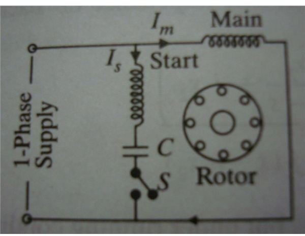
Click here to view a capacitor start motor circuit diagram for starting a single phase motor. Single phase motors work on the same principle as 3 phase motors except they are only run off one phase. Wondering how a capacitor can be used to start a single phase motor. Also read about the speed torque characteristics of these motors along with its different types. 3 φ motor runs from 1 φ power but does not start. Diagram dd6 diagram dd7 m 1 ln e diagram dd8 ln e l1 l2 l3 sc z1 u2 z2 u1 cap.
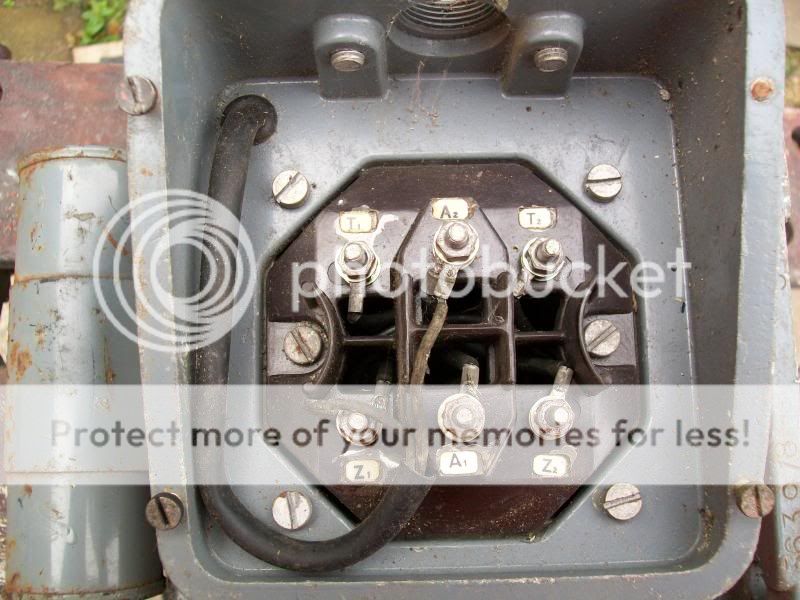
It mean terminal cooper plate w2u2 and v2 connect in one linehere i attached picture about motor terminal in star position. It may be hand started in either direction coming up to speed in a few seconds. However it will not self start. Electric motor wire marking connections. Because of this a true single phase motor has zero starting torque. Thermal contacts tb white m 1 z2 yellow z1 blue u2 black u1 red bridge l1 and l2 if speed controller sc is not required m 1 ln e white brown blue l1 l2 n sc.
For specific leeson motor connections go to their website and input the leeson catalog in the review box you will find connection data dimensions name plate data etc.
Gallery of Single Phase Motor Clutch Plate Connection