Note that symbols are discussed in detail later. It is also common for a control cabinet to supply a higher voltage to other equipment such as motors.
Motor Starter Wiring Diagram Template
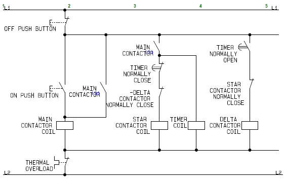
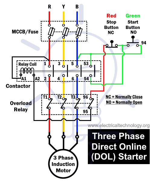
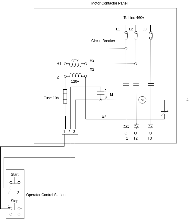
Basic motor control wiring diagram. Dashed lines indicate a single purchased component. The basic operation of the stopstart circuit is to provide a means of remotely controlling a motor operated load from a panel that only contains the low voltage control circuitry. A three wire control circuit uses momentary contact startstop stations and a normally open seal in contact connected in parallel with the start button to maintain. Figure 1 is a typical wiring diagram for a three phase magnetic motor starter. It actually looks like a bowl of spaghetti like if you unwound it and made it a straight line it would go from here to the moon. Basic wiring for motor contol circuitry of a starter two wire control two wire control circuits or low voltage release one of the common control wiring circuits used is known as two wire or low voltage release lvr.
They can be used as a guide when wiring the controller. This video walks you through the basic 2 wire and 3 wire control for 3 phase motor controllers. Electrical 0 christopher pumo. Motorcycle wiring simplified the basic diagram. Basic wiring for motor control technical data. Unit 1 basic principles of motor controls unit 1introduction this unit discusses the basic concepts of motor control including motor control language and the types of wiring diagrams used.
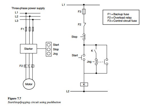
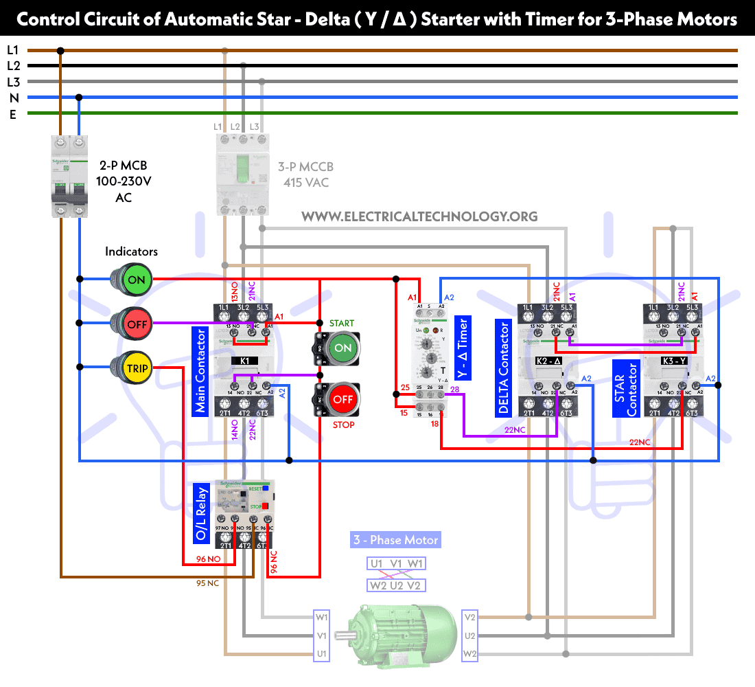
Motor control circuits motor control circuits are an effective way to reduce cost by using smaller wire and reduced amperage. They show the relative location of the components. In this particular case i show a low voltage control circuit and a 3 phase higher voltage motor. Have you ever flipped to the back of your motorcycle manual and looked at the stock or factory motorcycle wiring diagram. In the next episode in this series of videos we will add multiple start stop stations and demonstrate via the onscreen live simulated schematic how they work in the motor control circuit wiring. Three phase motor connection stardelta y δ reverse forward with timer power control diagram starting stopping of 3 phase motor from more than one place power control diagrams control 3 phase motor from more than two buttons power control diagrams.
Figure 1 typical wiring diagram. It utilizes a main tained contact type of pilot device such as a thermostat float switch or presence sensor. A very common form of latch circuit is the simple start stop relay circuit used for motor controls whereby a pair of momentary contact pushbutton switches control the operation of an electric motor. An example of a wiring diagram for a motor controller is shown in figure 1.
Gallery of Basic Motor Control Wiring Diagram