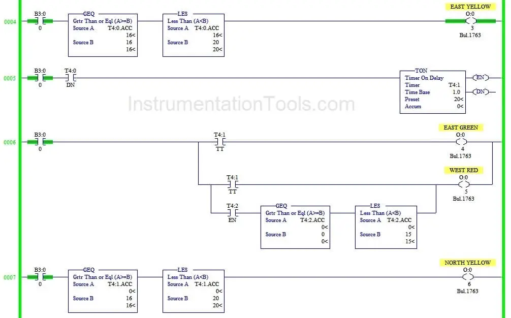
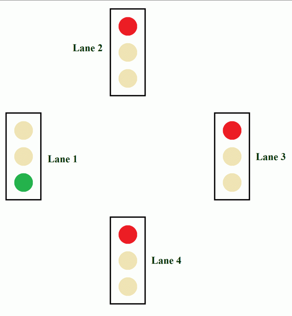
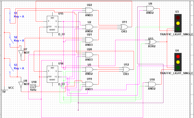
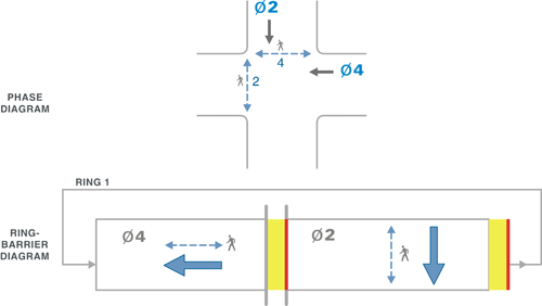
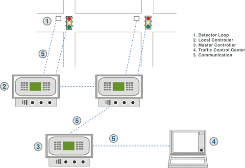
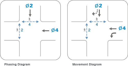
Traffic signal design handbook. Circuit diagram of traffic light control mini project.
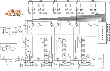
Index 387 Circuit Diagram Seekic Com
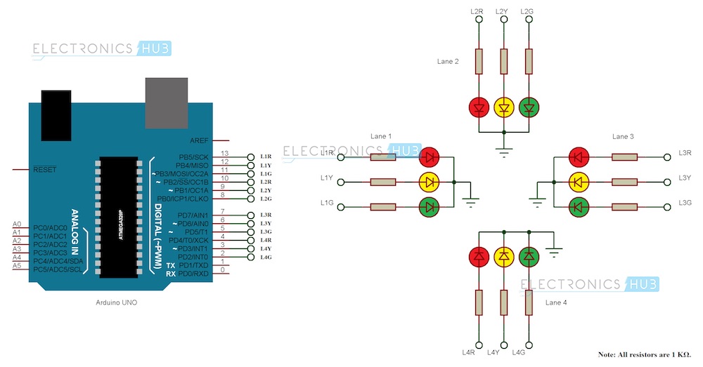
Circuit diagram of 4 way traffic signal. October 14 2010 may 2013 update. Traffic signal lights are very important to regulate vehicles and traffic on roads simple four way traffic light circuit is designed with timer ic 555 and counter ic cd4017. First of all make the connections as shown in circuit diagram. In4007 diodes 8 pieces circuit diagram and explanation. Jlcpcb for 2 pcb fabrication 2 day build time on. Circuit diagram for arduino traffic light controller there are total of 12 leds used in this project.
Wiring a shop traffic light the easy way duration. Now provide power supply. The timer here generates pulses of time period 100ms approximately. Very important ihave just got a patent for energy saving aperatus for traffic signal using less than 9 watt of electric with 12 to 24 volts terific power saving weight total less. The circuit allows you to control 2 or 4 way traffic allowing for two traffic lights north and south or four traffic lights north south east and west. There are two options for purchasing this circuit.
Working of two way traffic light circuit. We know each traffic signal light setup will have three colors and representing red for stop yellow for wait and green for go those signals are works based on time intervals. Red led 4 pieces blue led 4 pieces and yellow led 4 pieces cd4017 decade counter ic. You may also purchase additional traffic lights separately. Automatic street light circuit. Rs10 traffic light signal control sequencer install operation.
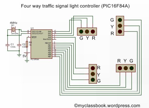
Four way traffic light circuit diagram using 555 timer ic is shown in the above diagram. Following figure shows the functional diagram of 7432 ic. These are circuit only and circuit including traffic lights x 2. Hammerdown motorsports 2529 views. In this circuit we are providing input signal to ic1 that is 4017 with the help of switch. The first thing we have to do is simply connect four set of red green yellow leds to respective pins of pic16f84a microcontroller as shown in circuit diagram.
Each signal has 3 leds red yellow and green connected to it through the 220 ohm resistors. Did you get that 4 way traffic control systemif so can you please send it to me. Bureau of maintenance and operations. In our circuit we are utilizing only 2 gates. In this project we are going to operate control a four way traffic light signal using pic16f84a microcontroller. Click image to enlarge.


