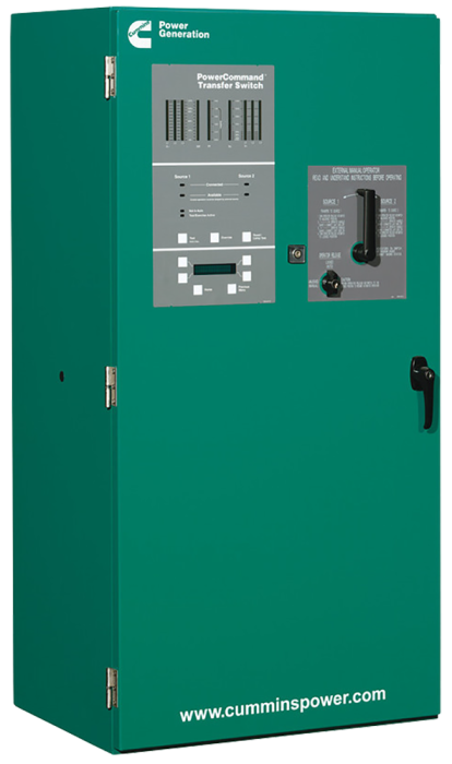
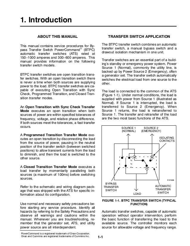
Paired with a powercommand generator set the result is a robust power system capable of ensuring reliable performance while maximizing cost effectiveness. This manual covers models produced under the cummins.
New 125 Amp Cummins Automatic Transfer Switch Oteca 208v S
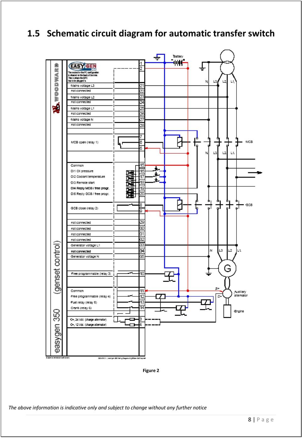
Cummins transfer switch wiring diagram. A 2 pin plug connec tor 323 1678 02 is shipped with the 1512 amp transfer switch battery charger. It reveals the elements of the circuit as streamlined forms and also the power and signal links between the devices. Construction is provided with the same rugged switch mechanism din rails relays and control as the standard gtec. The switch monitors both power sources signals generator set startup automatically transfers power and returns the load to the primary power source when the utility returns and stabilizes. Variety of cummins transfer switch wiring diagram. S 1464 0618 transfer switch mechanism transfer switch mechanism is electrically operated and mechanically held in the source 1 and source 2 positions.
Notice local electrical codes and regulations. The utility disconnecting device is not provided as part of the generator set or automatic transfer switch and cummins power generation accepts no responsibility for providing the means of isolation. A wiring diagram is a simplified conventional photographic depiction of an electric circuit. Transfer switch must be performed only by an electrician or authorized service representative. The transfer switch incorporates electrical and mechanical interlocks to prevent inadvertent interconnection of the sources. A wiring diagram is a simple visual representation in the physical connections and physical layout associated with an electrical system or circuit.
The location and wiring must comply with the contract drawings. Www page 3 of 6. Refer to the wiring diagram supplied with the generator set. Otpc transfer switches are available with closed transition transfer. Cummins transfer switch wiring diagram what is a wiring diagram. It shows how the electrical wires are interconnected and may also show where fixtures and components might be connected to the.
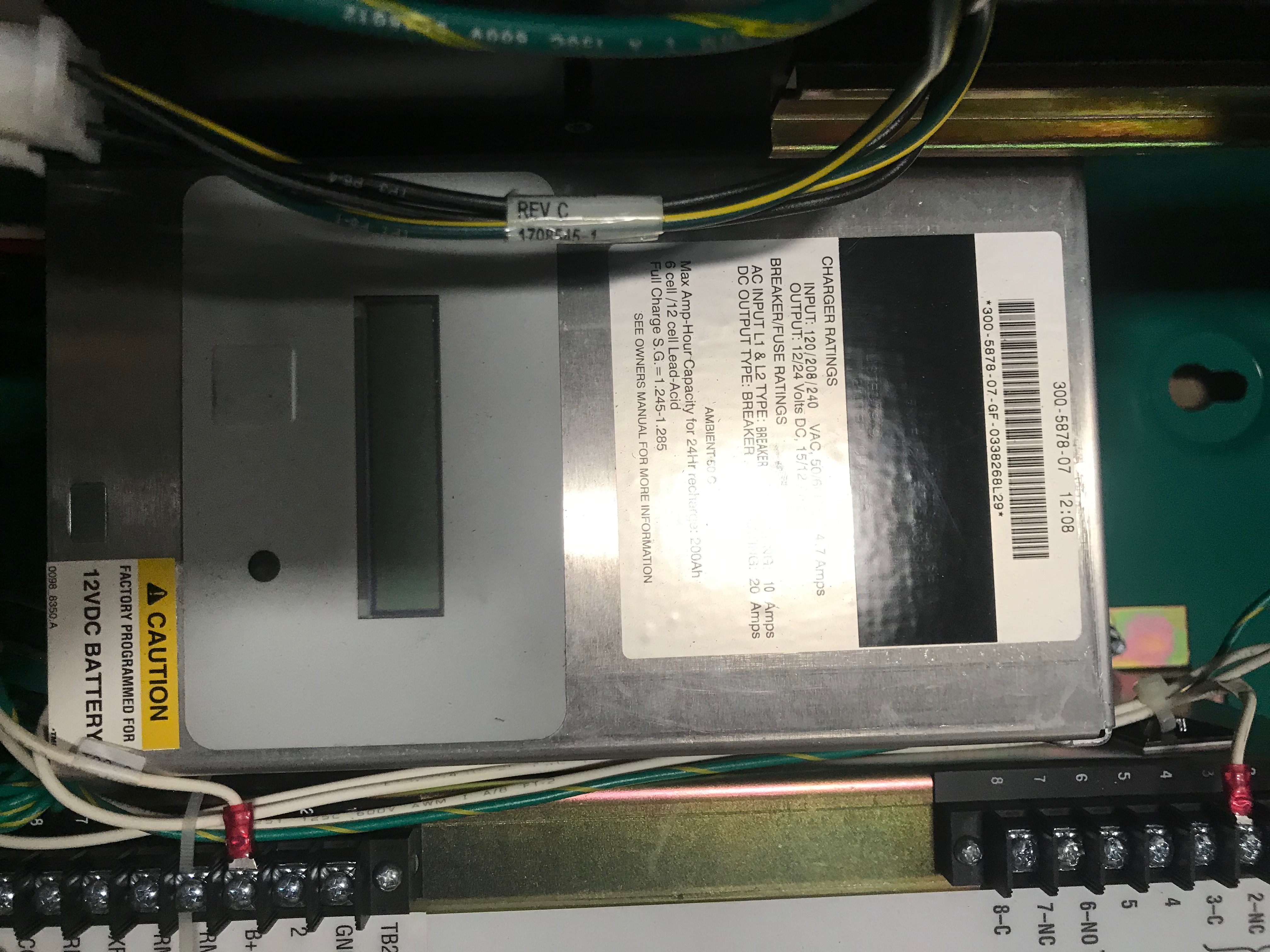
Integrated transfer switches for reliable power transitions at cummins we engineer our transfer switches with flexibility and ease of operation in mind. Can be used by wiring a fault indicator to the fault alarm output connector located on the front of the battery charger see figure 1. The powercommand micro processor control monitors utility and emergency standby generator set. The type of entrance switch.



__99834.1558655700.jpg?c=2)

