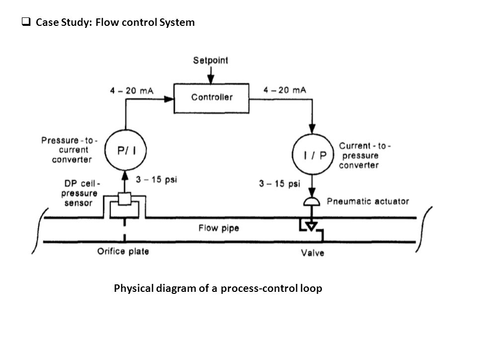
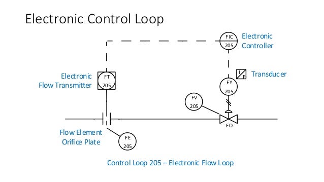
The process is illustrated in sections. The diagram below shows a typical flow control loop.
Food Loop Diagram Wiring Diagram Images
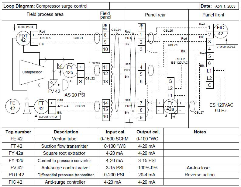
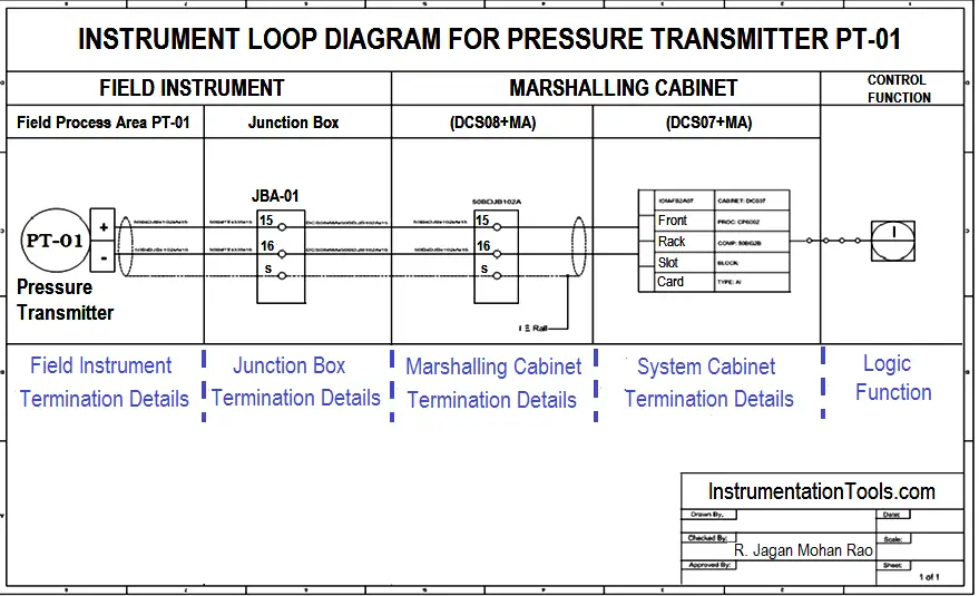
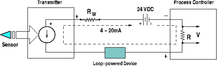
Loop wiring diagram for flow control loop. The flow of water is analogous to the flow of electrons or current. These set of drawings are more detailed than process and instrument diagrams pids. 2 wire loop powered transmitter current loops. When a tap inside your home is turned on there is a subsequent flow of water. Loop diagram symbols and pids pids and loop diagrams pids and loop diagrams are construction and documentation drawings that depict the flow of the process and illustrate the instrumentation control and measurement interactions wiring and connections to the process. It is possible to convey electrical power and communicate analog information over the same two wires using 4 to 20 milliamps dc if we design the transmitter to be loop powered.
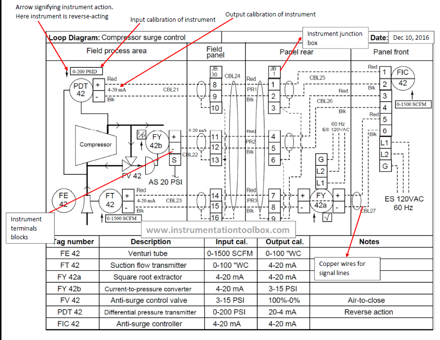
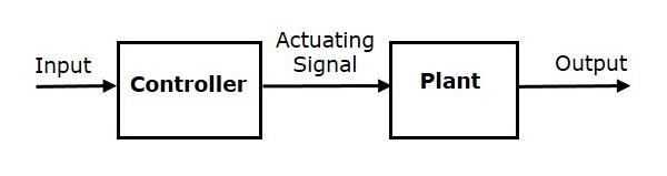
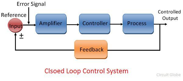
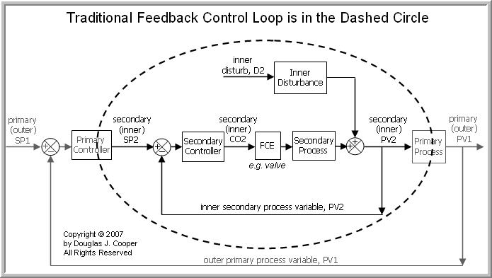
The 4 20 ma current loop is the prevailing process control signal in. When a loop diagram shows you exactly what wire color to expect at exactly what point in an instrumentation system and exactly what terminal that wire should connect to it becomes much easier to proceed with any troubleshooting calibration or upgrade task. A home heating system is simple onoff control with many of the components contained in a small box mounted on our. A loop powered transmitter connects to a process controller with only two wires which is why loop powered transmitters are synonymously known as 2 wire transmitters. The control function shown is an intermediate type such as a pid controller which means it can generate a full range of output signals anywhere between 0 100 rather than just an onoff signal. Home temperature control as shown below click for a large view the home heating control system described in this article can be organized as a traditional control loop block diagramblock diagrams help us visualize the components of a loop and see how the pieces are connected.
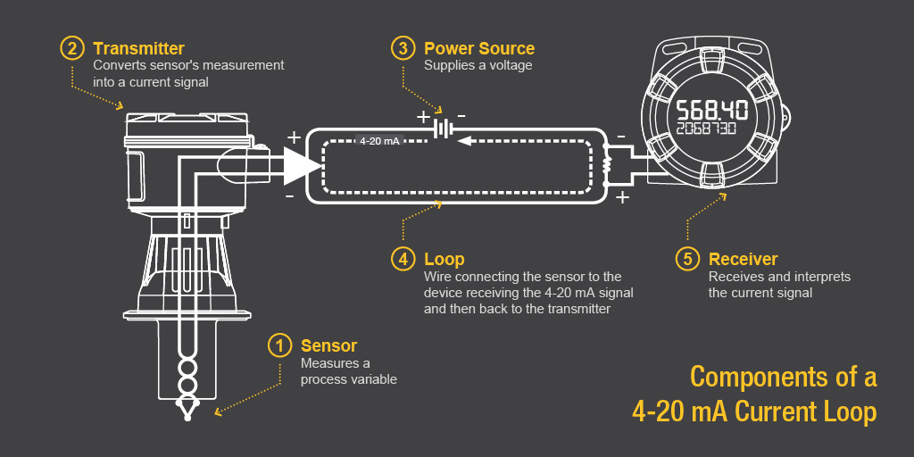
In this example a flow control loop is shown but can be level temperature or any one of many process parameters which need to be controlled. Loop diagrams are fairly constrained in their layout as per the isa 51 standard. The signal travels through a wire loop to a receiver and the receiver displays or performs an action with that signal. Instrument loop diagrams are also called instrument loop drawings or loop sheets. 5 the control valvefcv that either opens or close based on the signal from the controller to either open or close to increase or decrease flow. Thus the loop diagram is the most detailed form of diagram for a control system as a whole and as such it must contain all details omitted by pfds and pids alike.
To the novice it may seem excessive to include such trivia as wire colors in a loop diagram. Loop diagrams are the most detailed form of diagrams for a control system and thus it must contain all details omitted by pfds and pids alike.
Gallery of Loop Wiring Diagram For Flow Control Loop