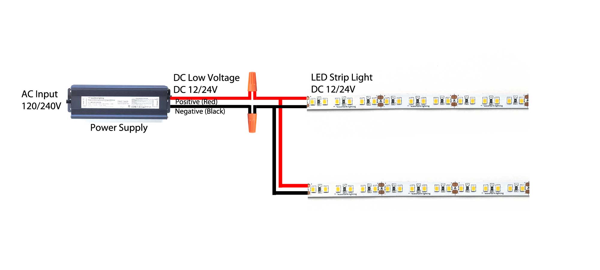
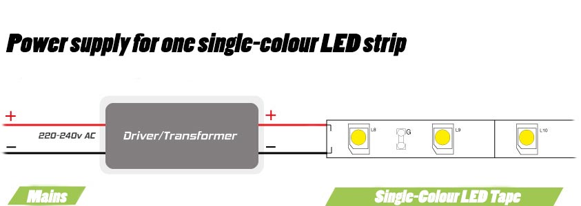
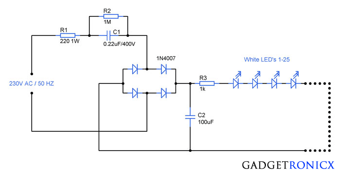
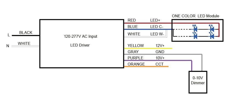
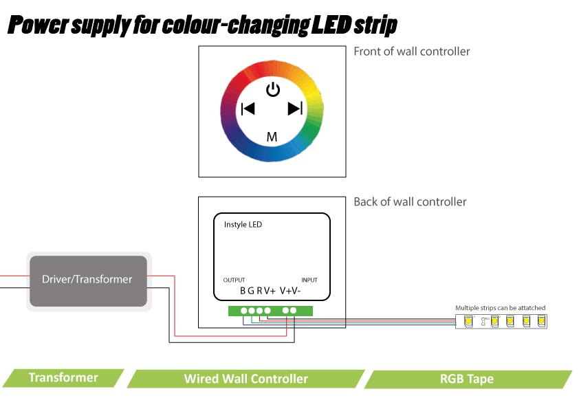
Finally the last led connection goes from the negative of the led to the negative output of the constant current driver creating a continuous loop or daisy chain. In electronics an led circuit or led driver is an electrical circuit used to power a light emitting diode led.

Led Toggle Switch Spst On Off
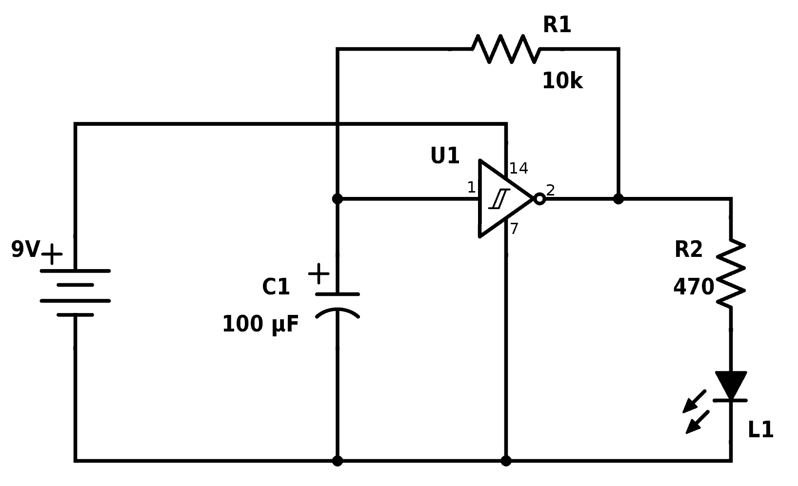
Led connection diagram. The circuit must provide sufficient current to light the led at the required brightness but must limit the current to prevent damaging the led. Circuit 3 of simple led circuits leds in parallel the final circuit in the simple led circuits tutorial is leds in parallel. The circuit diagram for leds in parallel connection is shown in the following image. Here are a few bullet points for reference about a series circuit. These are available in rgb and single color options and available in two three and four output connections. Add tip ask question comment download.
These led y connectors make it so you can plug in one power source and connect multiple led runs off it with a simple plug in connection. In this circuit we will try to connect three 5mm white leds in parallel and light them up using a 12v supply. When you are operating an led with 3v you have to use minimum 10 ohms resistor. The usual components in a wiring diagram are ground power supply wire as well as connection outcome tools buttons resistors reasoning entrance lights etc. 2760307 5mm red led 17 v 2760351 5mm yellow led 21 v 2760036 flasher red led 5 v 2760041 2 pack red led 26 v 2760086 jumbo red led 24v power supply i really didnt know what i would need to power them so i bought some 9v batteries and some 15v aas. I figured that would allow me to mix and match and make enough different voltage.
With leds you need accurate values for current voltage and resistance or the circuit will not work at all. You also need to make a large number of clean connections using delicate parts as opposed to. Wiring led lights can be a bit tricky because of the accuracy demanded in circuit values and the number of leds in a typical lighting circuit. It shows the parts of the circuit as streamlined forms and also the power and signal connections between the gadgets. For more details visit simple basic led circuit. A wiring diagram is a simplified standard pictorial representation of an electrical circuit.
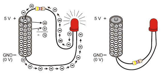
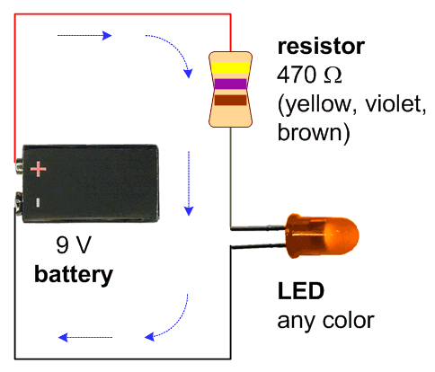
Assortment of t8 led tube light wiring diagram. An led must be connected in a circuit the right way around observe the polarity of the led. On the physical led the longer lead or leg of the led is the anode. The total voltage of the circuit is the sum of the voltages across each led. Simple led light emitting diode circuit diagram. A listing of electric signs and summaries could be found on the electrical sign page.
The way that the schematic symbol of the led maps to the physical led is shown in the diagram below. Same current flows through each led. The above diagram shows a 3v led circuit in this circuit there are two aa cells are used.
