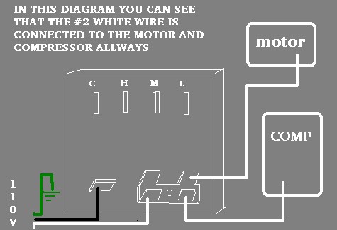
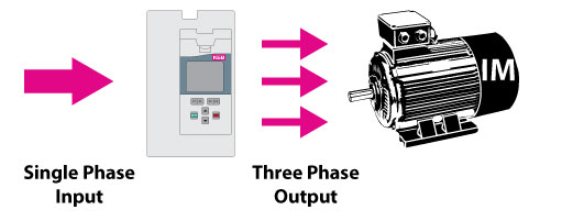
The confusion is all the wires are black. This one just exchanges the single phase for 3 phase.

5 Ton 3 Phase Zr57k3 Tf5 130 R22 Ac Compressor Century Ac Motor With Fan Amp Coil
3 phase ac compressor wiring diagram. Single phase motor wiring diagram with capacitor baldor single phase motor wiring diagram with capacitor single phase fan motor wiring diagram with capacitor single phase motor connection diagram with capacitor every electrical arrangement is made up of various unique pieces. How to repair electrical wiring neutral wire for a 220 volt furnace 2 wire and 3 wire cables wiring a 30 amp disconnect wiring a 3 phase air conditioner attic wiring for a security light wiring an electric shear bedroom electrical wiring wiring a building. This is different from a single phase compressor which will have 3 terminals listed as s r and c start run and common. The compressor should have 3 electrical terminals attached to the housing from inside the compressor. A main concern is the amperage requirements of the compressor. See the picture for reference.
There are many air conditioning and heat pump brands in the market but one common component is the compressor. We used a pressure switch by square d part number 9013 fhg12mix. Variety of ac compressor wiring diagram. After 3 months the motor burnt out. Each component ought to be placed and linked to different parts in particular manner. This video is part of the heating and cooling series of training videos made to accompany my websites.
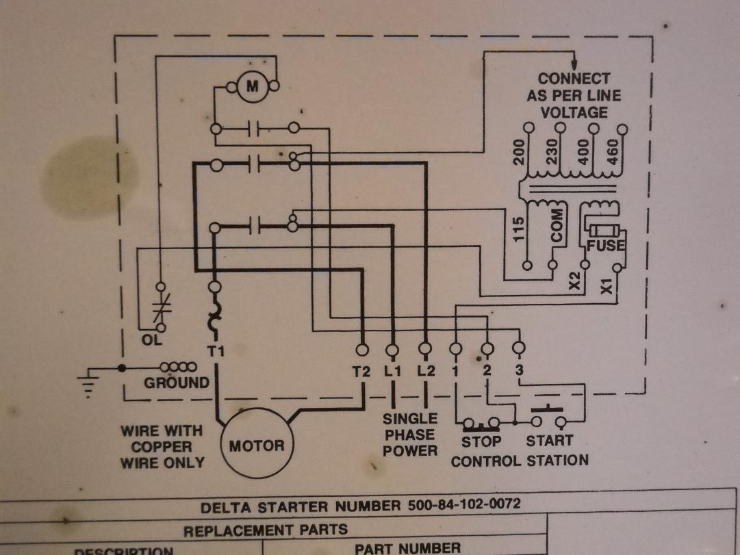
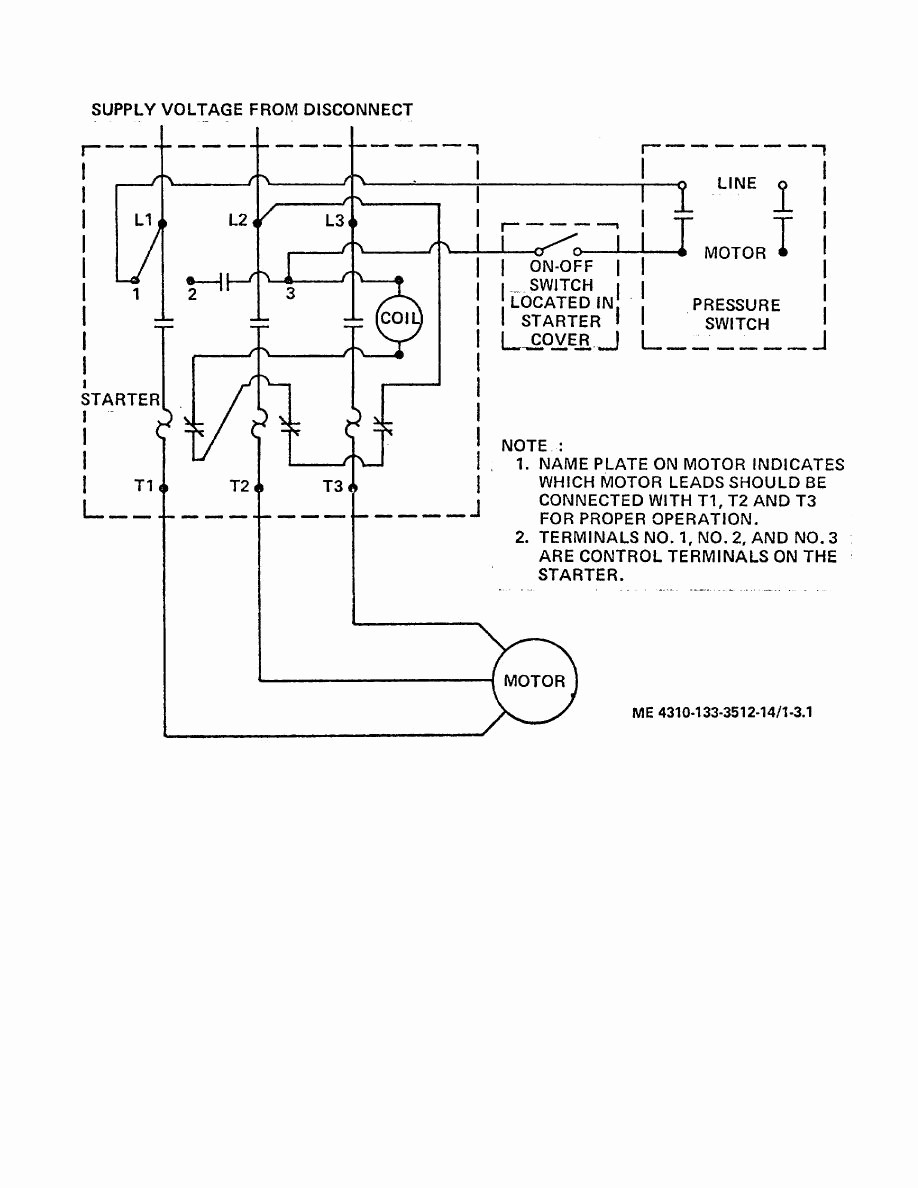
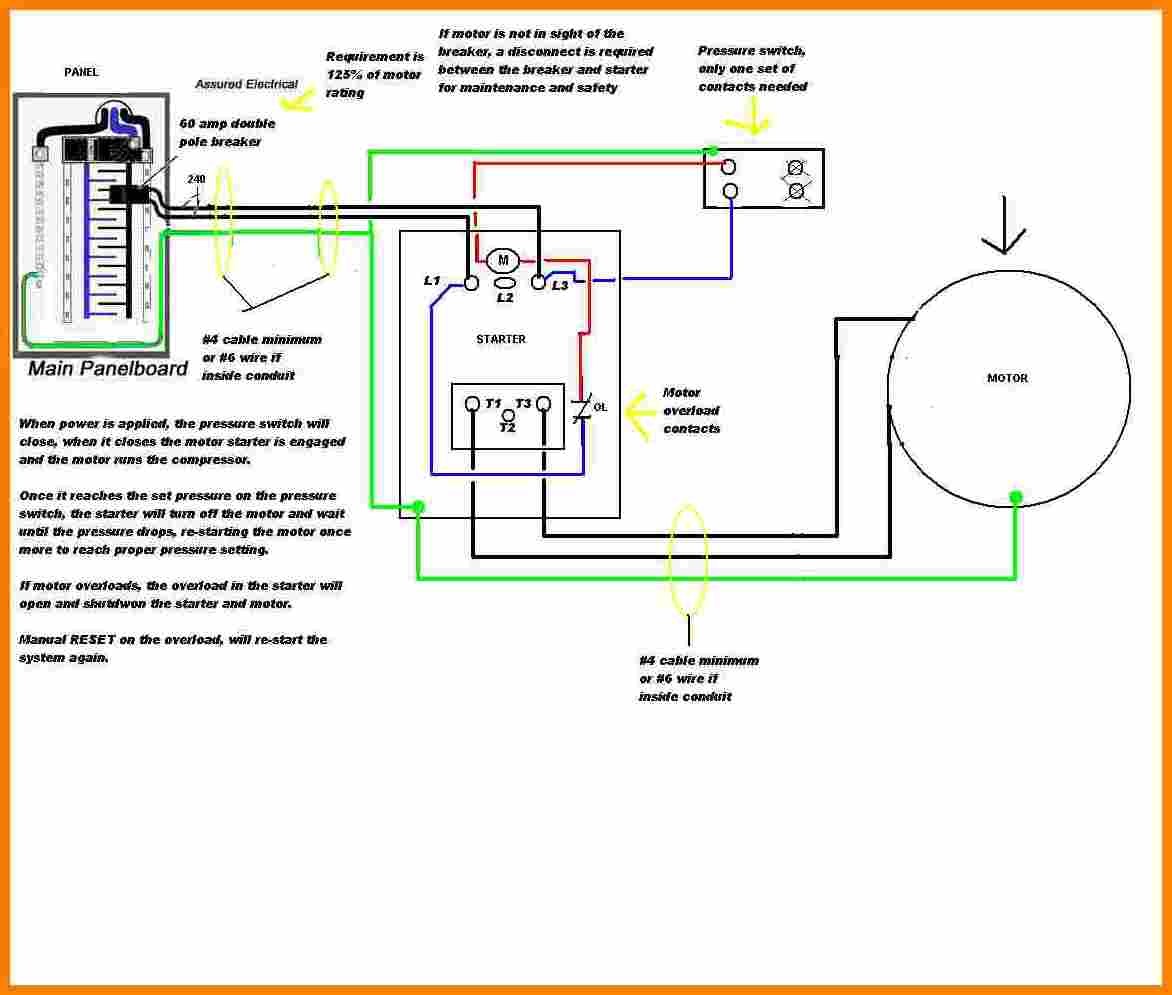
If you have a 120v coil instead of running a line from coil overload l2 you must run coil overload neutral. We are using a 3 phase 240 volt system and hooking up to an air compressor. 3 phase air compressor motor starter wiring diagram. And if so can it make the compressor run backwards. This dictates the size of the wires. W2 cj2 ui vi wi w2 cj2 ui vi wi a cow voltage y high voltage z t4 til t12.
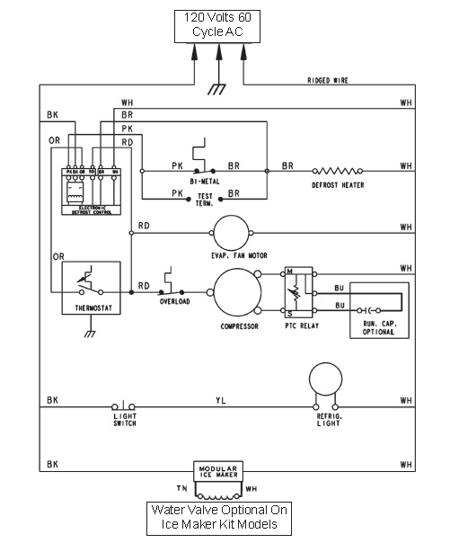
Another factor is if the compressor is single phase or three phase power. Most use the copeland compressor which usually has 3 terminals l1 l2 which are your. It reveals the elements of the circuit as simplified shapes as well as the power and signal connections in between the tools. Single phase wiring diagrams always use wiring diagram supplied on motor nameplate. Three phase wiring diagrams always use wiring diagram supplied on motor nameplate colored leads are only applicable on the new rolled steel motor lines. A wiring diagram is a streamlined standard photographic representation of an electric circuit.
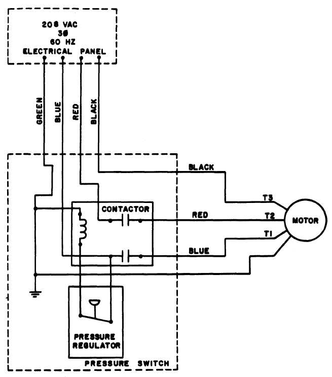
How to wire a 3 phase ac unit. On a 3 phase compressor you will see the terminals listed as t1 t2 and t3. While wiring a compressor there are a number of things to consider for a proper electrical hook up. This dictates the configuration of the wiring. The red wire from the 3 phase is only connected to the motor. The black and blue wires from the 3 phase are connected to the pressure switch and then connected to the motor.
