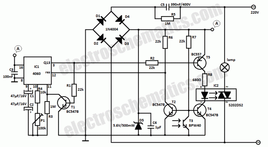
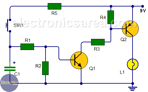
This light sensor switch circuit allows the automatic connection of a lamp when the light is low at nightfall and will maintain the lamp on for a certain period of time. This switch type is widely popular.

Cn 3010 Light Sensor Switch Circuit P Marian 06 12 2011 This
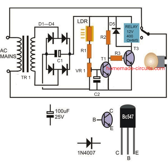
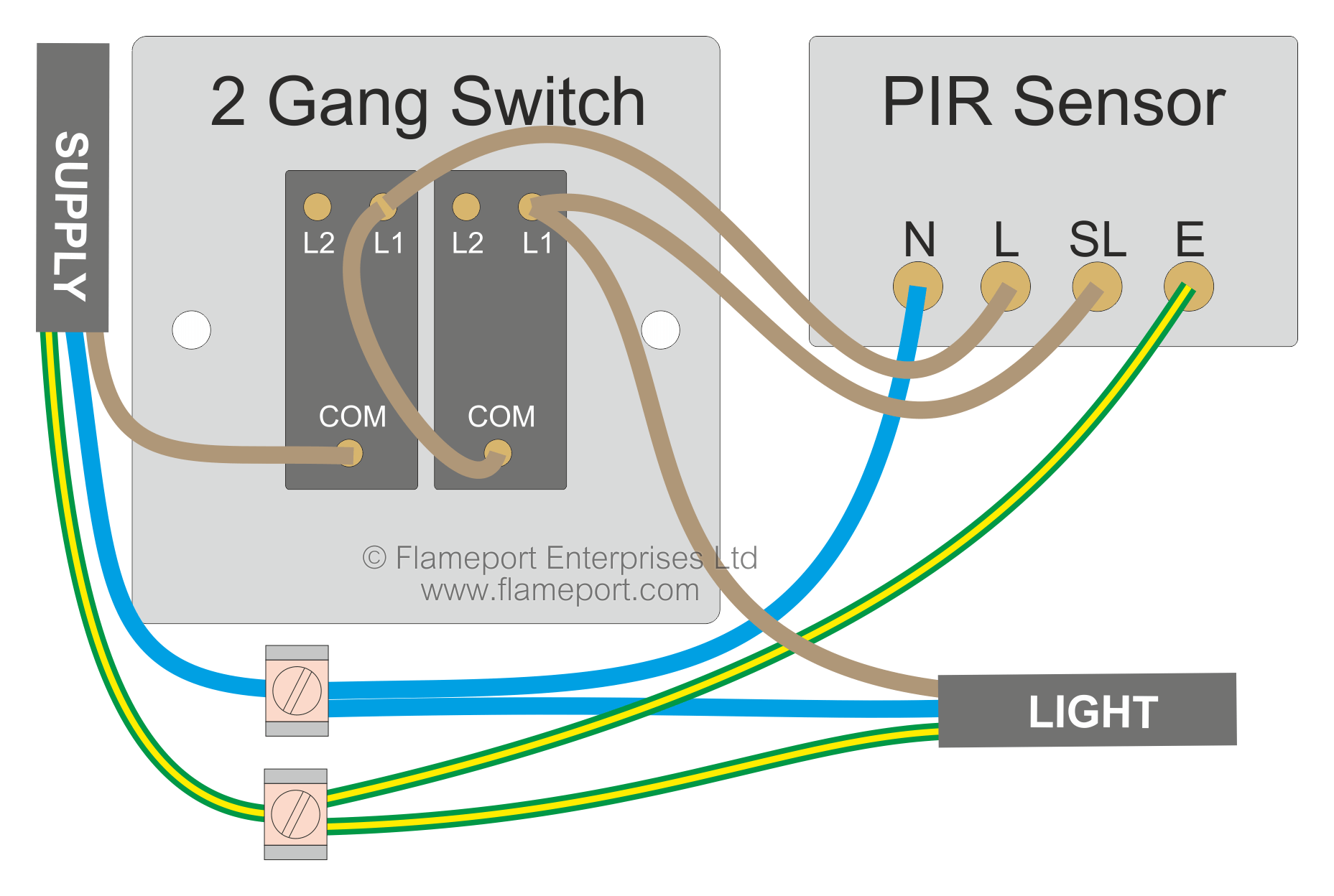
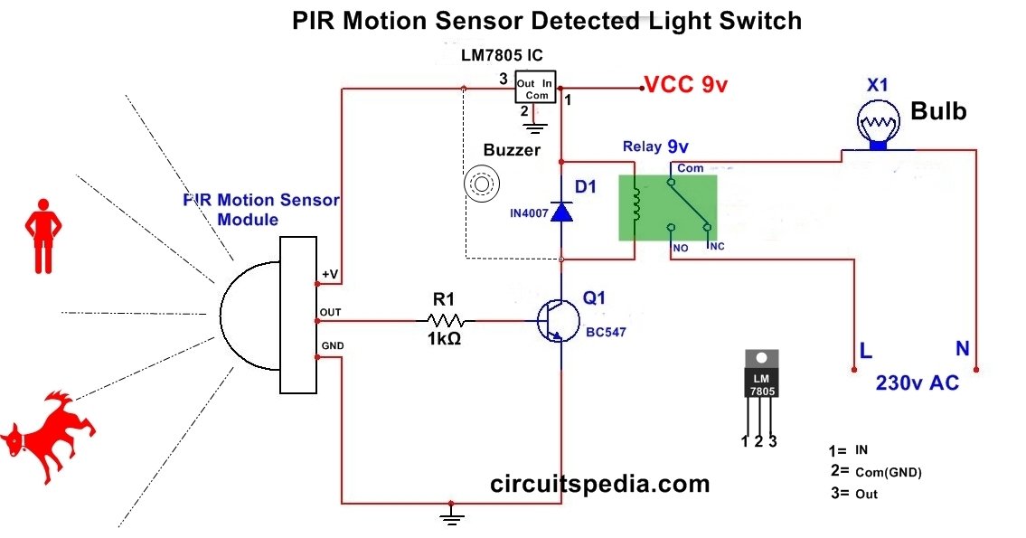
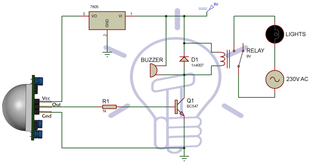
Light sensor switch circuit diagram. Both illustrations include additional light fixtures. Circuit diagram of the pir motion sensor light and switch based on sb0061 shown here can be used for security or corridor lighting in power saving mode. The source is at sw1 and 2 wire cable runs from there to the fixtures. The light sensor circuit is an electronic circuit designed using light sensor ldr darlington pair relay diode and resistors which are connected as shown in the light sensor circuit diagram. Light sensor circuit working operation. A wiring diagram is a simplified conventional pictorial depiction of an electrical circuit.
The 12v dc supply required for the whole circuit can be fed from any standard 12v ac mains adaptorbattery. It reveals the elements of the circuit as streamlined shapes and also the power and also signal connections between the tools. We will experiment with the digital touch switch circuit using jk flip flop as rs flip flop. Photocell wiring diagram with contactor 7. Variety of motion sensor light wiring diagram. Today in this video i have shown how to make an automatic street light using triac bt136.
If you have a single light just eliminate the wiring that feeds the second fixture. A 230v ac supply is provided to the load in this case the load is represented with a lamp. Street light pole connection diagram 4. The circuit shown in figure 1 is a very simple light sensor circuit that will activate an led when the ldr in the circuit receives light. The switch is a semiconductor relay s202ds2 and the oscillator is 4060. The hot and neutral terminals on each fixture are spliced with a pigtail to the circuit wires which then continue on to the next light.
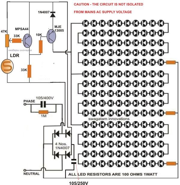
20 led running light circuit. The circuit shown in figure 2 is using a relay at its output and when light falls on the ldr it will activate the relay. Sensor light switch schematic. No relay no battery components required bt136 diac db3 you can get it from old cfl driver 220k. If a light fixture is closer to the switch the method shown in figure c is probably best. 8 simple touch switch circuit projects.
Just use your finger to touch them only also can turn on off circuit. This time can be adjusted with p1 between 1 and 5 hours. Electric pole box connection 5. This diagram illustrates wiring for one switch to control 2 or more lights. If your sensor will be placed close to the switch the method shown in figure b is probably best for you. Day night sensor switch circuit 8.
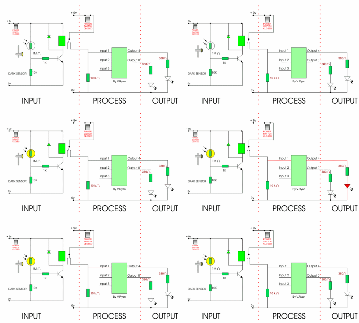
Photocell wiring diagram 6. Working of the circuit is simple and straight forward. A simple touch on and off switch circuit. Multiple light wiring diagram. The figures below are showing two different light sensor circuits.

