Receiver circuit is connected to ac appliance via relay so that we can control the light remotely. Traditionally control zoning and future rezoning was limited by lighting circuit wiring.

Outdoor Garden Led Solar Light Circuit
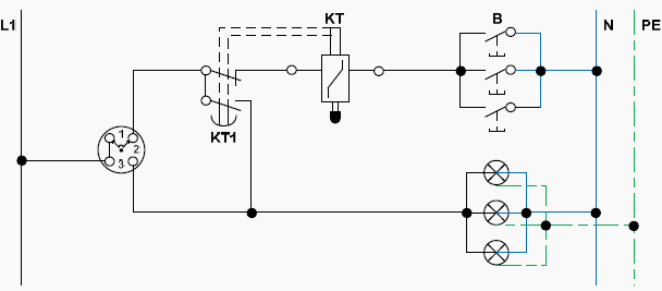
Lighting control circuit diagram. The tunnel circuit control the lamps in four ways as follow. Control of a lighting circuit from three or more points. In tunnel wring circuit diagram we have used spdt two way switches to control the lighting points in tunnels and corridors. We have used ic 4017 to convert it into a push on push off switch. In this remote controlled switch circuit we are using tv remote to onoff the ac light by pressing any button of remote and using the tsop1738 at receiver end. From 7am to 6pm only the middle one bulb will glow and the first and last one will turned off.
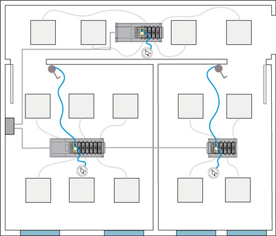
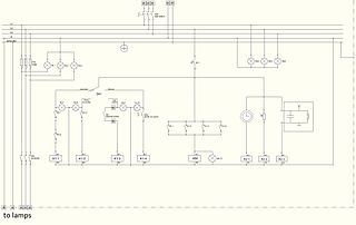
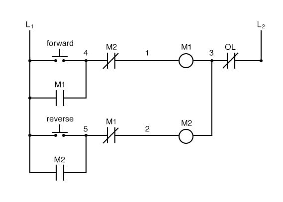
One line diagram of simple contactor circuit control onoff circuit diagram of typical electrically held lightingheating contactor a contactor is an electr. Outside lights may be controlled by motion detectors and photo cells switched from one or more locations. This unit will automatically switch the lights off after a preset delay if no motion is detected. To operate an external lamp with the same circuit interface a relay with the output pin3 of the 555 ic. Advances in communications enable relatively economical zoning as granular as individual luminaires or ballastsdrivers and zoning and rezoning using software instead of hardwiring. This type of circuit is used in large rooms long corridors staircases and generally in large rooms.
Automatically control lighting in offices private restrooms and employee break rooms. A wiring diagram is a streamlined standard photographic depiction of an electric circuit. Outside lighting wiring diagram how to install wiring for outdoor lighting a separate dedicated circuit may not be necessary or required. It shows the parts of the circuit as simplified shapes and also the power as well as signal connections between the tools. During normal light in the day ie. Switching lighting circuit allerretour with two extreme switches and one or more intermediate switches.
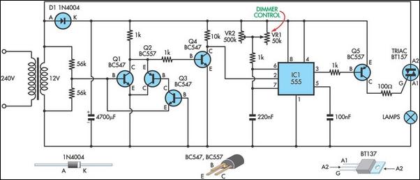
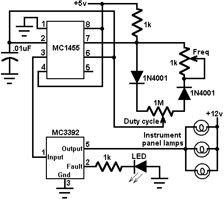
So it can control 230v ac lights or similar externally powered lights with the same circuit. Here is the circuit diagram of a very versatile emergency lamp that can be operated in two modes flasher and dimmer. Assortment of crestron lighting control wiring diagram. Each sensor employs a special 180 multi segmented lens and pir motion detector circuit to detect motion. The circuit is based on the read more. The relay can be connected similarly as shown in that circuit.
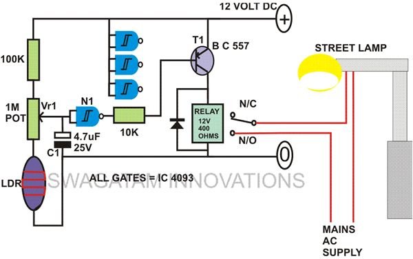
For relay interface refer the circuit diagram of the automatic power cut off circuit.

