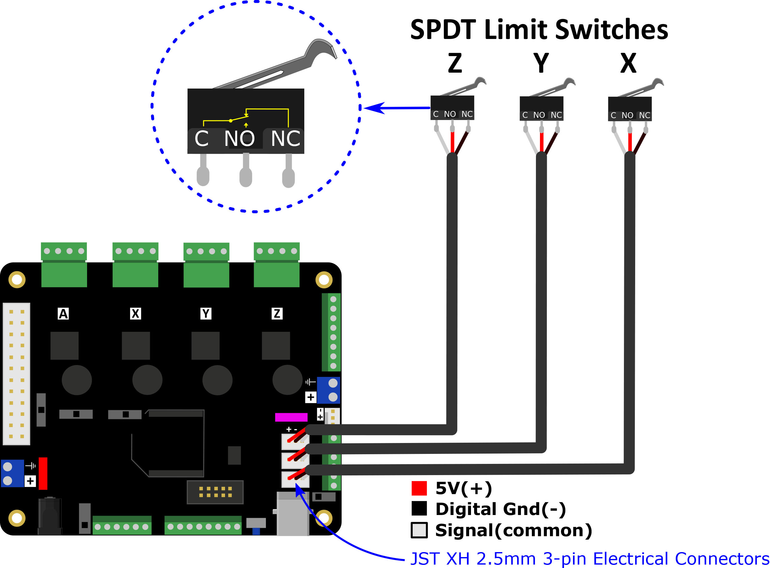
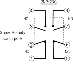
Wiring limit switches arduino tutorial the limit switches are used to detect the physical limits of the working area and to position more detail for grbl cnc. It has three terminals.
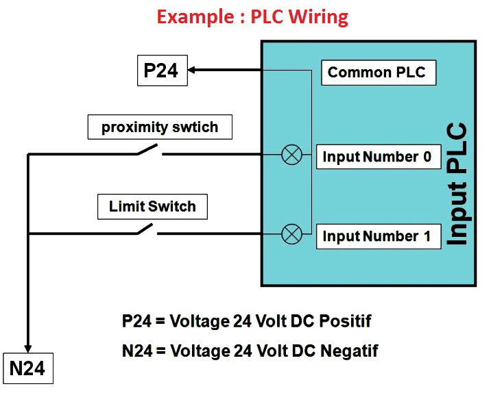
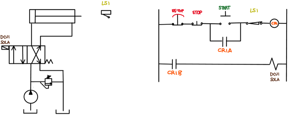
Plc Input Output Wiring Diagram Programmable Logic
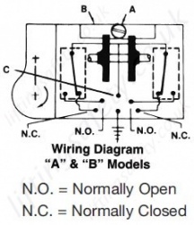
Limit switch diagram. Non plug in switches differ from plug in switches in that the switch body and receptacle are one piece as seen with the sensor below. Limit switches are generally composed of five components. Limit switch is a switch operated by the motion of a machine part or presence of an objectthey are used for control of a machine as safety interlocks or to count objects passing a point. The power input terminal is called the common terminal and is used to connect the switch to a power source. We have accumulated several images ideally this image is useful for you and assist you in finding the solution you are searching for. Limit switch styles 6.
Honeywell fan limit switch wiring diagram thanks for visiting my website this blog post will discuss concerning honeywell fan limit switch wiring diagram. It is abbreviated com the other terminals are the normally open no. The structure of a typical vertical limit switch is shown in the following figure as an example. The wiring in a non plug in switch is brought in through the. Standardized limit switches are industrial control components manufactured with a variety of operator types including lever roller plunger and whisker type. The shapes of limit switches are broadly classified into horiz ontal vertical and multiple limit switches.
Structural diagram of typical vertical limit switch seals actuator head built in. A limit switch is used to control electrical devices by breaking and completing electrical circuits. The operating head is still a separate piece.
