Basics 9 416 kv pump schematic. Dashed lines indicate a single purchased component.

Mcc Wiring Diagram H1 Wiring Diagram
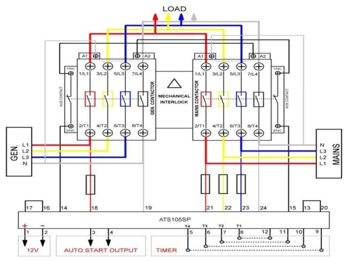
Mcc panel wiring diagram pdf. Wiring diagram for bms ddc panel vnd592vxkglx. The three phases are then connected to a power interrupter. Basics 6 72 kv 3 line diagram. A diagram that represents the elements of a system using abstract graphic drawings or realistic pictures. This system uses 3 phase ac power l1 l2 and l3 connected to the terminals. Basics 8 aov elementary block diagram.
Basics 10 480 v pump schematic. Electrician circuit drawings and wiring diagrams youth explore trades skills 3 pictorial diagram. Yeah even lots of wiring representations are supplied this circuitry diagram can swipe the reader heart a lot. Panel boards and wiring november 2019 100. Dear visitors when you are hunting the new mcc panel wiring diagram electrical wiring diagram collection to read this day mcc panel wiring diagram can be your referred circuitry layout. Mcc panel wiring diagram and panel ga sample free download as pdf file pdf text file txt or view presentation slides online.
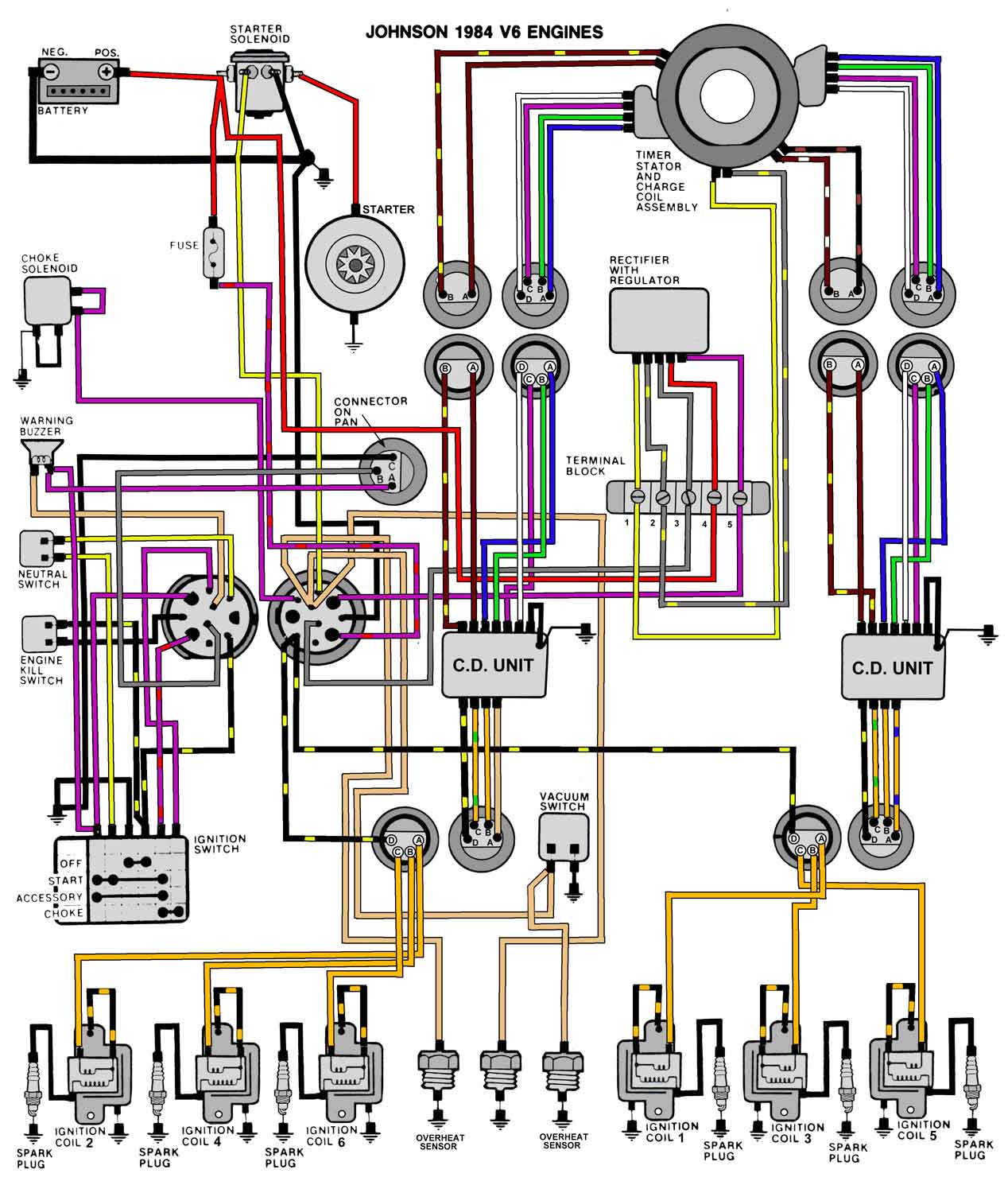
Mcc panel wiring diagram and panel ga sample november 2019 265. Home current explore explore all. Basics 11 mov schematic with block included basics 12 12 208 vac panel diagram. An example of a wiring diagram for a motor controller is shown in figure 1. Basics 13 valve limit switch legend. A line diagram gives the necessary informa tion for easily following the operation of the various devices in the circuit.
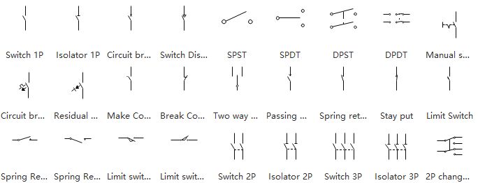
Note that symbols are discussed in detail later. Basics 5 480 v mcc 1 line. Bms riser diagram for hvac system december 2019 181. A diagram that uses lines to represent the wires and symbols to represent components. Basics 7 416 kv 3 line diagram. A wiring diagram gives the necessary information for actually wiring up a group of control devices or for physically tracing wires when trouble shooting is necessary.
It is a great aid in trouble. Wiring diagram book a1 15 b1 b2 16 18 b3 a2 b1 b3 15 supply voltage 16 18 l m h 2 levels b2 l1 f u 1 460 v f u 2 l2 l3 gnd h1 h3 h2 h4 f u 3 x1a f u 4 f u 5 x2a r power on optional x1 x2115 v 230 v h1 h3 h2 h4 optional connection electrostatically shielded transformer f u 6 off on m l1 l2 1 2 stop ol m start 3 start start fiber optic. This drawing include the sample sld wiring panel general arrangement diagram.


