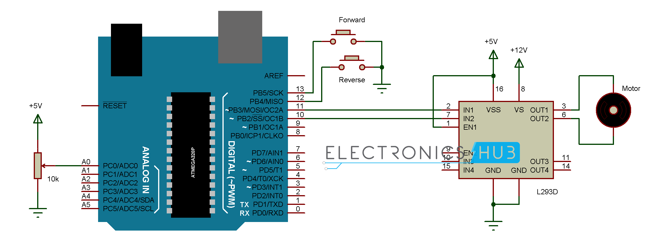
A wiring diagram is used to represent how the circuit generally appears. Basic wiring for motor control technical data.
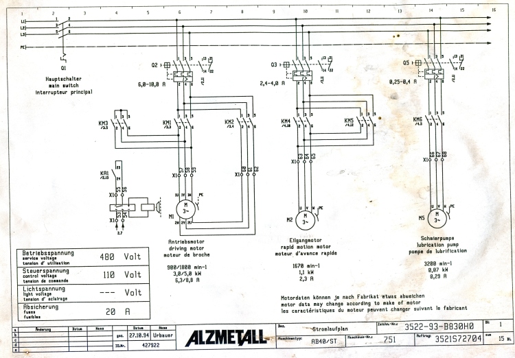
Contactor Wiring Diagram Brake H1 Wiring Diagram
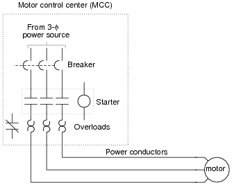
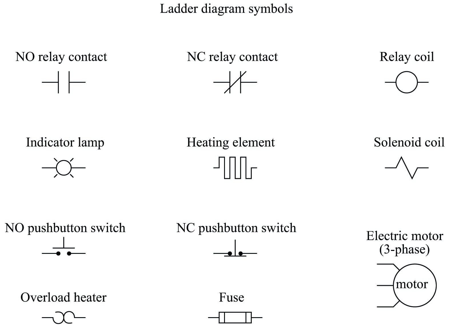
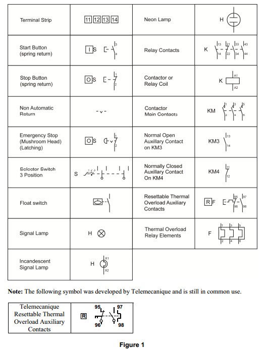
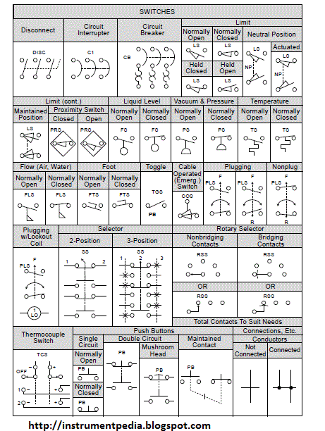
Motor control wiring diagram symbols. Wiring diagrams show the connections to the controller. Basics 13 valve limit switch legend. Based on your observations of these two diagrams explain how electromechanical relays are represented differently between ladder and schematic diagrams. Also explain the operation of this motor control circuit. Basics 14 aov schematic with block included basics 15 wiring or connection. Rockis 2001 wiring diagrams wiring connection diagram a diagram that shows the connection of an installation or its component devices or parts.
Wiring diagrams sometimes called main or construction diagrams show the actual connection points for the wires to the components and terminals of the controller. Basics 10 480 v pump schematic. Basics 9 416 kv pump schematic. Wiring diagrams show as closely as possible the actual location of each component in a circuit including the control circuit and the power circuit. To check out a wiring diagram first you need to recognize what basic components are included in a wiring diagram as well as which pictorial icons are used to represent them. Three phase motor connection stardelta y δ reverse forward with timer power control diagram starting stopping of 3 phase motor from more than one place power control diagrams control 3 phase motor from more than two buttons power control diagrams.
Motor control wiring diagram pdf wiring diagram is a simplified usual pictorial representation of an electrical circuitit shows the components of the circuit as simplified shapes and the facility and signal associates with the devices. The common components in a wiring diagram are ground power supply cord and connection outcome gadgets switches resistors reasoning gateway lights etc. Electric motor controls g. Basics 7 416 kv 3 line diagram. Basics 11 mov schematic with block included basics 12 12 208 vac panel diagram. To help illustrate the differences between wiring diagrams and schematics a basic control circuit will first be explained as a schematic and then shown as a wiring diagram.
Basics 8 aov elementary block diagram. Interpret this ac motor control circuit diagram explaining the meaning of each symbol.


