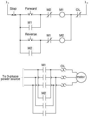
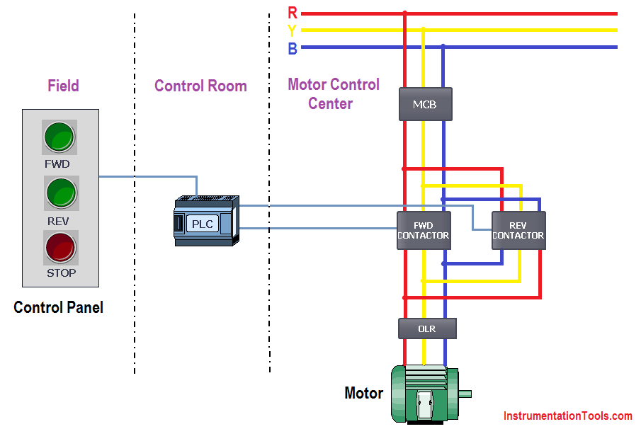
If interlock not required then simply remove the symbol from the diagram and connect with simple. The above figure shows the physical layout of motor starter however this would be designed through ladder logic in this plc tutorial.
Plc Implementation Of Forward Reverse Motor Circuit With
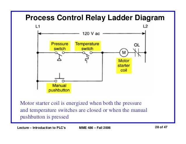
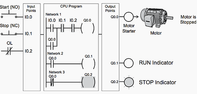
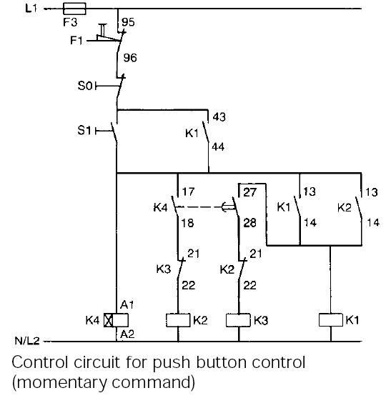
Motor starter ladder diagram. In this convention the hot and neutral power conductors are drawn as vertical lines near the edges of the page with all loads and switch contacts drawn between those lines like rungs on a ladder. Wiring diagrams show the connections to the controller. Basic wiring for motor control technical data. The motor is to be controlled from a startstop pb station that also contains a green pilot light to indicate the status of the mps relay. With a selector switch a. Wiring diagrams sometimes called main or construction diagrams show the actual connection points for the wires to the components and terminals of the controller.
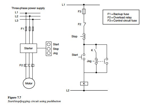
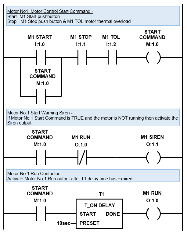
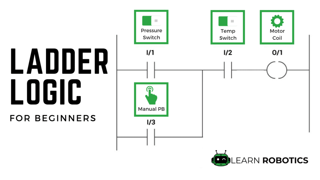
Above figure does not show limit switch because it depends on external interlock like say level switch flow switch pressure switch etc depending on application. In a ladder diagram components are arranged according to their physical position in the installation. When electric motor is started it draws a high current typical 5 6 times greater than normal current. Motor contactor or starter coils are typically designated by the letter m in ladder logic diagrams. Ladder diagram for dol direct on line motor starter. Which of the following types of motor starters connects the motor directly to the supply line on starting.
Still commonly used in many factories the dol or direct on line motor starter is another way of starting ac motors. A 3 phase motor is to be protected against phase loss phase imbalance or low voltage using a square d mps type relay. In dc motors there is no back emf at starting therefore initial current is very high as compared to the normal current. An alternative to the conventional schematic diagram in ac power control systems is the ladder diagram. Basic of the dol starter. This video builds on the standard 3 wire circuit by incorporating multiple stopstart stations.
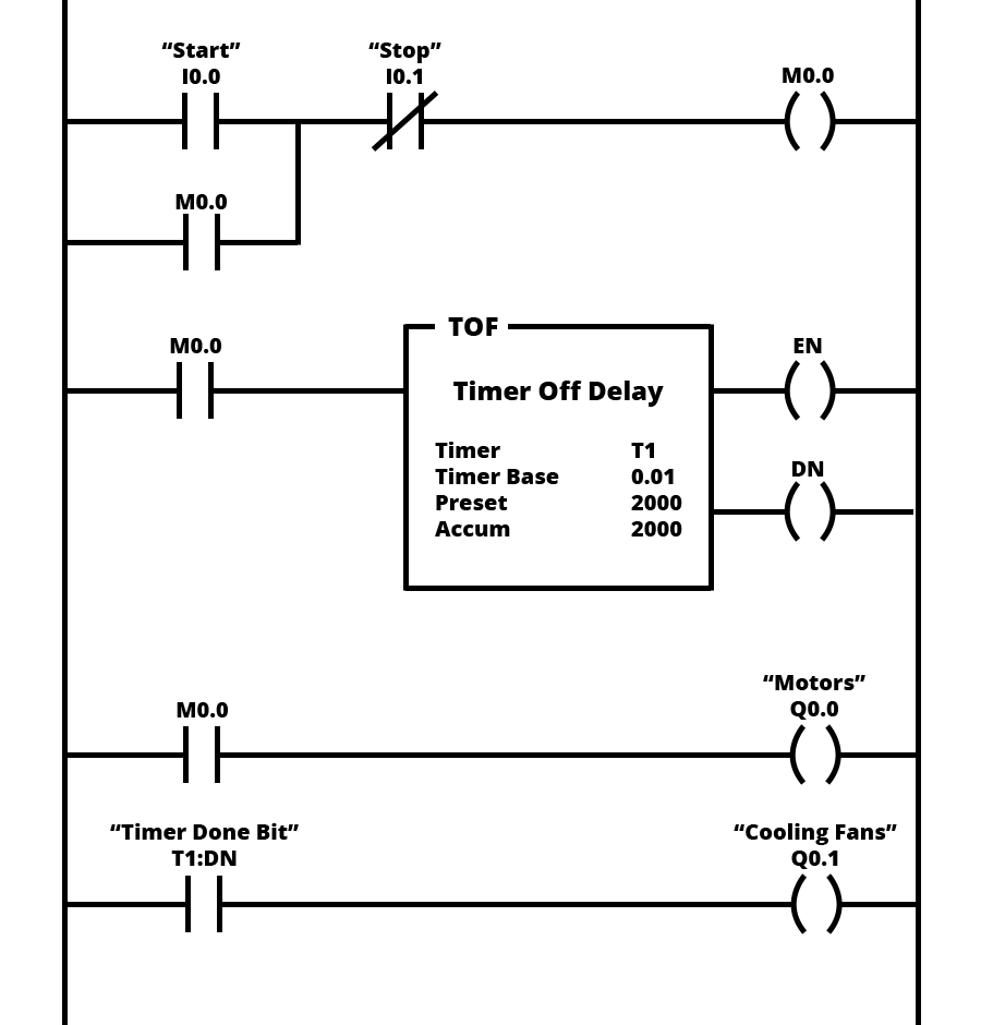
Continuous motor operation with a momentary start switch is possible if a normally open seal in contact from the contactor is connected in parallel with the start switch so that once the contactor is energized it. At least one load much be included in each rung of a ladder diagram. This is what needs to be included in my ladder diagram. The dol is made of a contactor usually 3 phase contactor an overload relay like the thermal relay and some connections in between. In the previous article we have learned about the control diagram of the dol starter and now in this article we will learned about the ladder diagram of the dol starterdol direct on line starter is used to start the motor by applying full line voltage to the motor. To protect the motor from these high starting currents we use a star and delta starter.
Gallery of Motor Starter Ladder Diagram