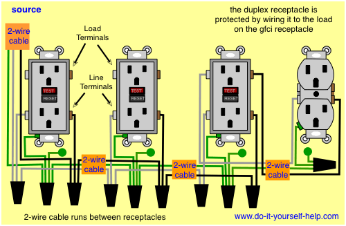
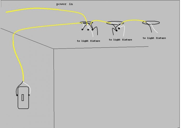
This diagram shows the wiring for multiple switched outlets on one switch. The source for the circuit is at the switch and 2 wire cable runs to each receptacle outlet.

Wiring Gfci Receptacles In Series Wiring Diagram Images
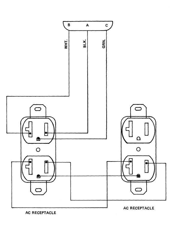
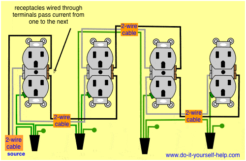
Multiple outlet wiring diagram. For wiring in series the terminal screws are the means for passing voltage from one receptacle to another. Wiring multiple outlets diagram gfci wiring diagram multiple size. Multiple outlet in parallel wiring diagram. Right here are a few of the leading drawings we receive from different sources we really hope these pictures will be useful to you as well as hopefully very appropriate to just what you desire concerning the multiple outlet wiring diagram is. Any break or malfunction in one outlet will cause all the other outlets to fail. The neutral wire from the circuit is shared by both sets.
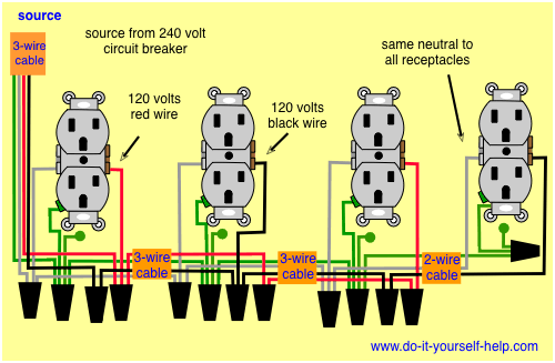
800 x 600 px source. Wiring a plug basic electrical wiring electrical circuit diagram electrical plan electrical projects electrical installation electrical outlets 3 way switch wiring outlet wiring. Here 3 wire cable is run from a double pole circuit breaker providing an independent 120 volts to two sets of multiple outlets. Wiring diagram for dual outlets. Twist clockwise using pliers then screw a wire cap onto the connection. Wiring diagram for multiple switched outlets.
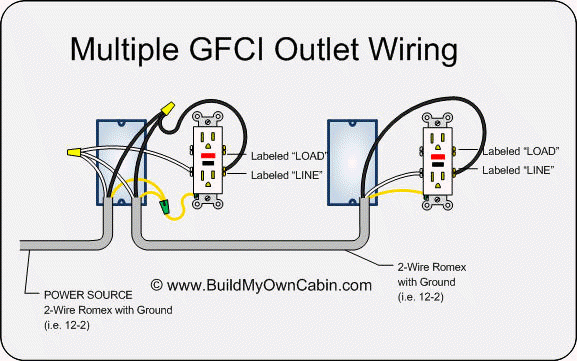
You create a pigtail by twisting together multiple wires of the same color its very important that theyre the same color and adding a short length of spare wire of that color. At the outlets each is wired using a pigtail splice to make the hot and neutral connections. This wiring is commonly used in a 20 amp kitchen circuit where two appliance feeds are needed such as for a refrigerator and a microwave in the same location. Another approach to outlet wiring is to create pigtails. Multiple gfci outlet wiring diagram. Multiple outlet in serie wiring diagram.


/electricity-and-power-in-greece-1526374-final-5c3df84e46e0fb00013b5f11.png)


