Horns strobes chimes bells klaxons speakers circuit. This would be your addressable loop circuits.
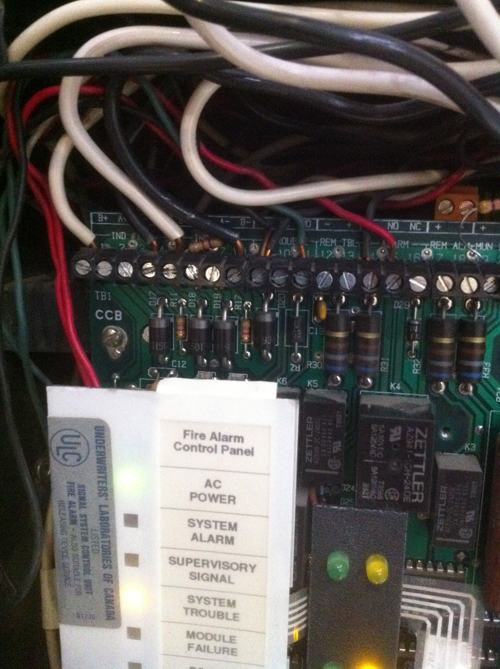
End Of Line Testing Do S And Don T S Part 4
Nac circuit wiring. Firenet plus wiring instruction 1 v101. Below is a circuits diagram that displays the circuit styles of a notification appliance circuit nac. Each circuit is capable of being independently controlled by the 4009 idnet as commanded by the host panel. In the fire alarm industry there are three types of fire alarm wiring circuits. Below is a circuits diagram that displays the circuit styles of a signaling line circuit slc. This would be your hornstrobe or speaker circuits off of remote power supplies addressable fire alarm panels signal modules bell cards etc.
Nac is the acronym for notification appliance circuit. Click here for more information on fire alarm wiring idc initiating device circuits click here for more information on fire alarm wiring nac notification appliance circuits. Are specific signals transmitted by an alarm system that indicate whether it has been armed or disarmed. In the fire alarm industry there are three types of fire alarm wiring circuits. The pad100 nac is a monitored notification appliance circuit that wires to the slc loop to provide an additional notification circuit. The pad100 nac is compatible with and potters iafcarc pa series addressable fire alarm control panels.
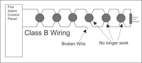
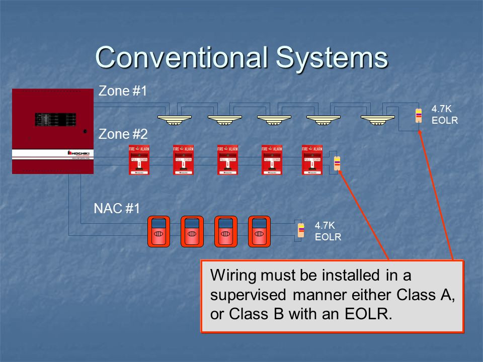
Also called the bell circuit signal circuit or output circuit. An open nac is a trouble on a fire alarm panel that shows that a wire in the building somewhere along the notification appliance circuit or horn strobe circuit has has broken wire or it has come loose from a screw terminal or splice. Tells people of a fire or other life threatening emergency appliance. Field wiring diagram for complete wiring compatible appliances current and line distance information. When used with a potter addressable releasing panel the pad100 nac can provide an. This circuit is usually a two wire circuit and makes use of an end of line resistor to end.
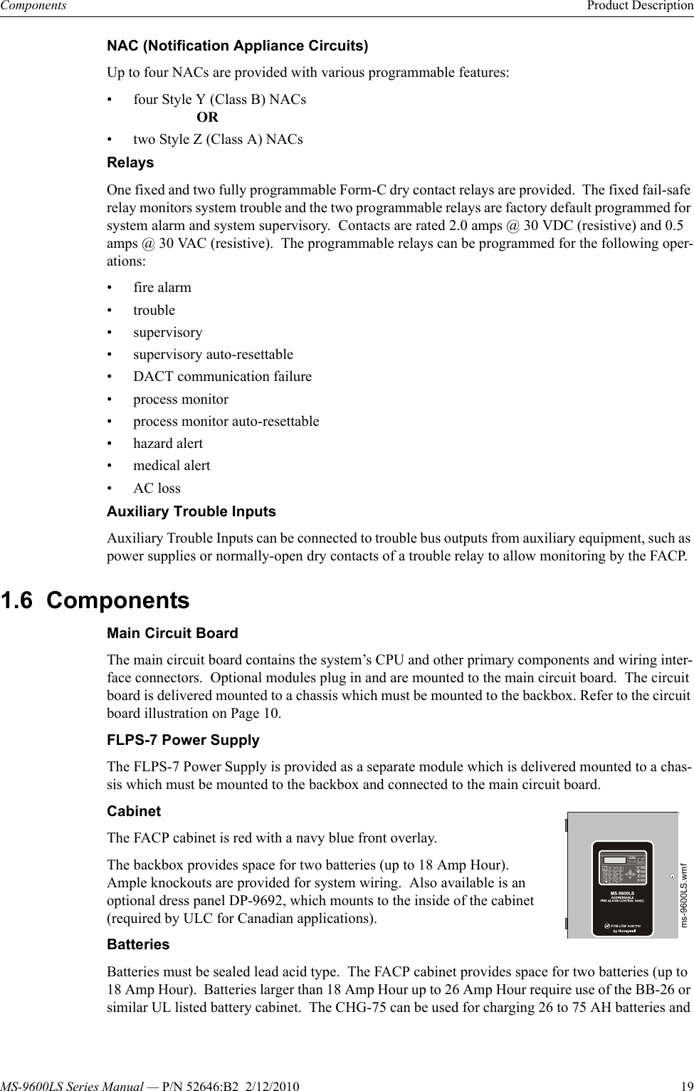
Short for notification appliance circuit. Output devices are terminated to the nac in either a class a or class b configuration. Physical wire loop carrying power to the notification appliances the nac circuit starts at the main fire alarm panel or at power expander panels and goes out to the notification devices in the. The notification circuits use a 10k end of line resistor for supervision. The nac circuit is designed to start at the main fire alarm panel and connects to the notification devices in the building or residence thereby completing the circuit. The total sum of device loads in the nac circuit must not exceed the maximum current specified for the firenet plus panel when operating in continuous regulated pulsed regulated or special application mode.
The nac circuit is usually a simple circuit which is designed by our expert engineers.


