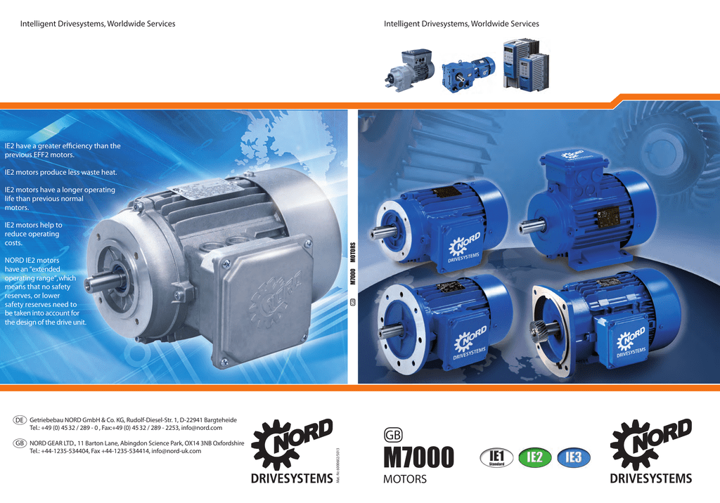
As indicated in the nord catalog each nord motor can be supplied with a number of brake torque sizes. Symbols that represent the ingredients inside the circuit and lines that represent the connections between.
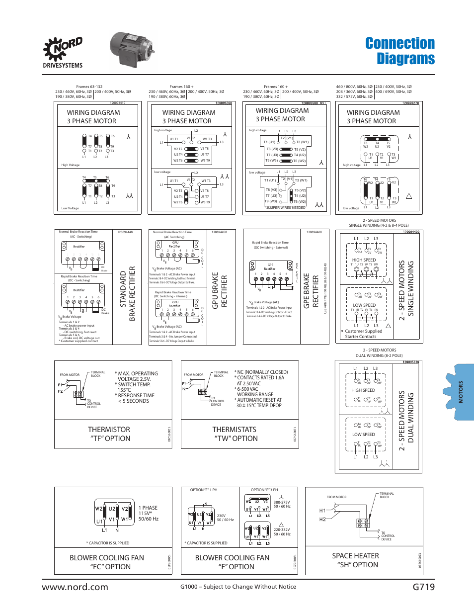
Connection Diagrams Brake Rec Tifier St And Ard Rec Tifier
Nord brake motor wiring diagram. Wiring diagrams are made up of certain things. If a single phase motor is single voltage or if either winding is intended for only one voltage the terminal marking shall be determined as follows. Nord gear corporation midwest 800 nord drive po box 367 waunakee wi 53597 phone. When using an ac drive with a brake motor select a brake motor with separate brake wires. 230yy460y volts 60 hz 200yy400y volts 50 hz. Connection diagram dt79 example motor voltages.
The bme can we wired to operate for. For most applications we advise sizing the brake to 15 2 times the motor rated torque. A wiring diagram is a schematic which uses abstract pictorial symbols showing each of the interconnections of components in the system. Nord motor wiring diagram whats wiring diagram. Mounting the motor casing onto the brake and fan completes. Nord relies on the equipment builder to specify appropriate brake sizing for their application while giving consideration to the following.
When a motors power supply is brought in from three wires instead of just one with the power delivery cycling through each of these in sequence hence the a part of ac it permits an effective power level that is 3 times higher about 1728 times higher than a. The bmk brake control system optional for frame sizes 71 to 225. Which allow the motor brake system to cycle at a very high rate. Terminal markings and internal wiring diagrams single phase and polyphase motors meeting nema standards b. Then use a separate full voltage power source brake contactor and proper circuit protection to control the brake. A three phase motor is more efficient than a single phase motor because of the peculiarities of alternating current ac.
3phase motor me dc break magnetic wiring diagram kese kare. Connect the brake supply cable inserted into the motor terminal box according to the diagram on the inside of the box cover while connecting the brake with the motor maintain all the necessary safety measures and precautions pertaining to the handling of electrical equipment 9. Always use wiring diagram supplied on motor nameplate. Also make sure the brake is powered released when the ac drive is running including accelerating at speed and decelerating the motor.


