In general however there are only a couple varieties used for wiring a residential home. Or canadian circuit showing examples of connections in electrical boxes and at the devices mounted in them.
Home Alarm Wiring For A New House
Normal house wiring diagram. Because a house is provided with alternating current the terms positive and negative do not apply as they do to direct current in batteries and cars. Without a switch wiring diagram it can be very easy to make a serious mistake that will cause the circuit to malfunction and possibly become a hazard. Typical house wiring diagram illustrates each type of circuit. A1 and b1 can burn not all the time but according to what the switches at a2 b2 and c2 say. The power can start at a fixture or either of the two switches. It moves along a hot wire toward a light or receptacle supplies energy to the device called a load and then returns along the neutral wire so called because under normal conditions its maintained at 0 volts or what is referred to as ground.
The hot and neutral terminals on each fixture are spliced with a pigtail to the circuit wires which then continue on to the next light. A2 is a normal single pole switch as seen by its two side screws. There are many ways to wire a 3 way switch. It is up to the electrician to examine the total electrical requirements of the home especially where specific devices are to be located in each area and then decide how to plan the circuits. Electricity travels in a circle. Live neutral tails from the electricity meter to the cu.
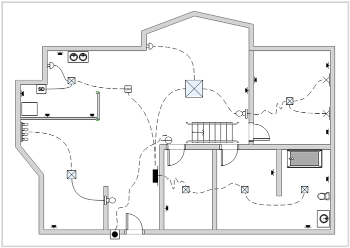
For simple electrical installations we commonly use this house wiring diagram. To understand the function that different wires in a circuit play consider first our use of terms. This diagram illustrates wiring for one switch to control 2 or more lights. In a typical new town house wiring system we have. When wiring a house there are many types wire to choose from some copper others aluminum some rated for outdoors others indoors. Ring circuits from 32a mcbs in the cu supplying mains sockets.
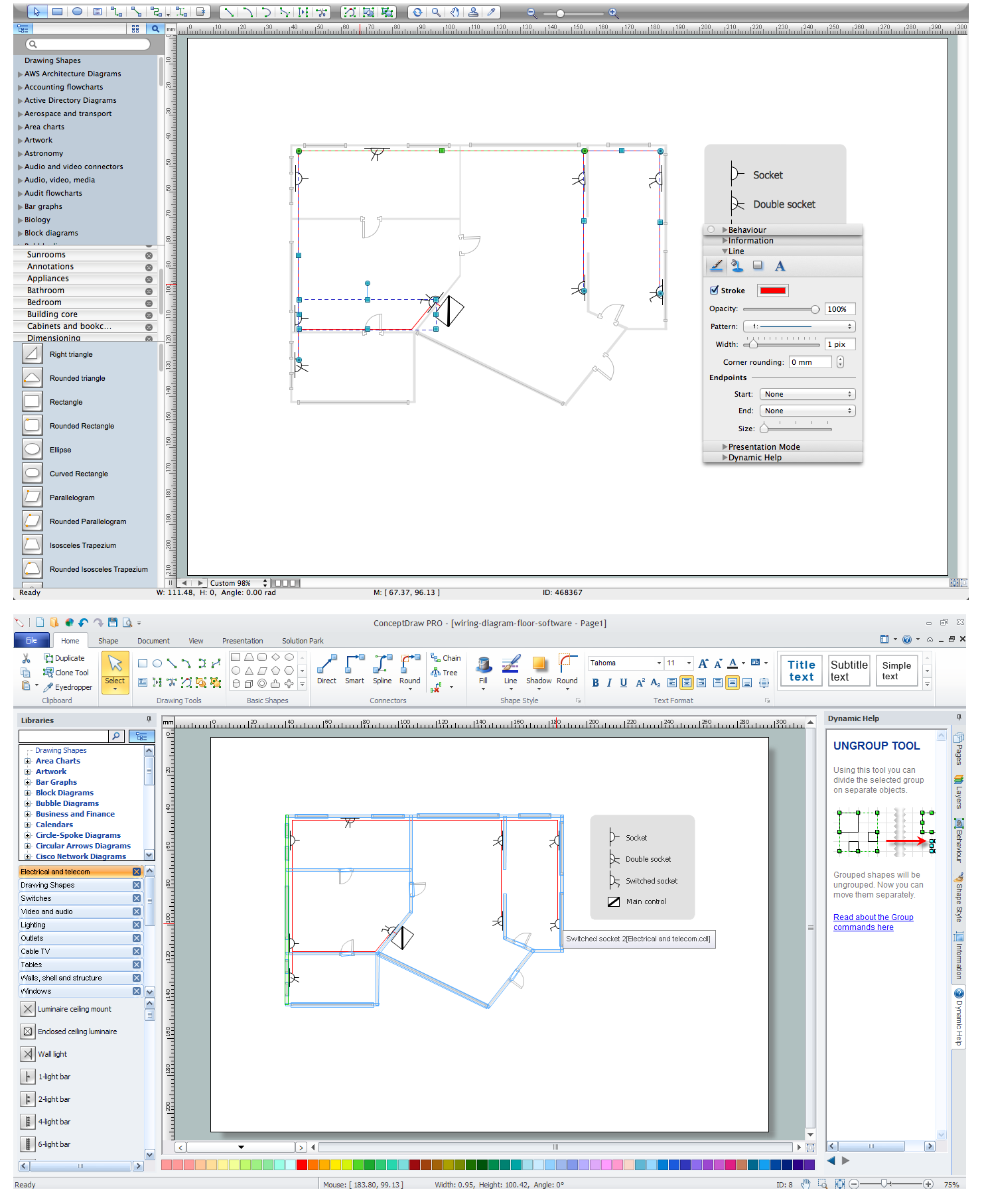
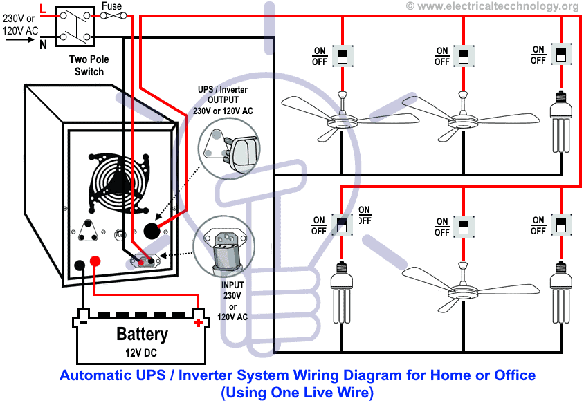
A typical set of house plans shows the electrical symbols that have been located on the floor plan but do not provide any wiring details. 2 such rings is typical for a 2 up 2 down larger houses have more. A split load cu. Electrical wiring is a tighter system a more closed system. Romex shown in yellow above is the trade name for a type of electrical conductor with non metallic. The image below is a house wiring diagram of a typical us.
Multiple light wiring diagram. On example shown you can find out the type of a cable used to supply a feed to every particular circuit in a home the type and rating of circuit breakers devices supposed to protect your installation from overload or short current. More about 3way switch diagrams. Having a map of your homes electrical circuits can help you identify the source of a problem. The source is at sw1 and 2 wire cable runs from there to the fixtures.
Gallery of Normal House Wiring Diagram


/cdn.vox-cdn.com/uploads/chorus_image/image/65890030/electrical_wiring_x_banneer.7.jpg)