In the on state a switch acts just like a piece of perfectly conducting wire. This in effect looks like an open circuit preventing current from flowing.

Touch On And Off Switch Circuit Electronics Circuit
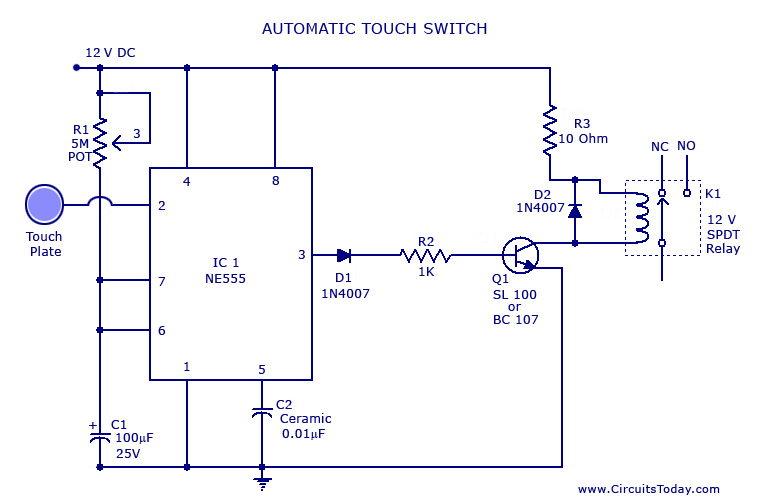
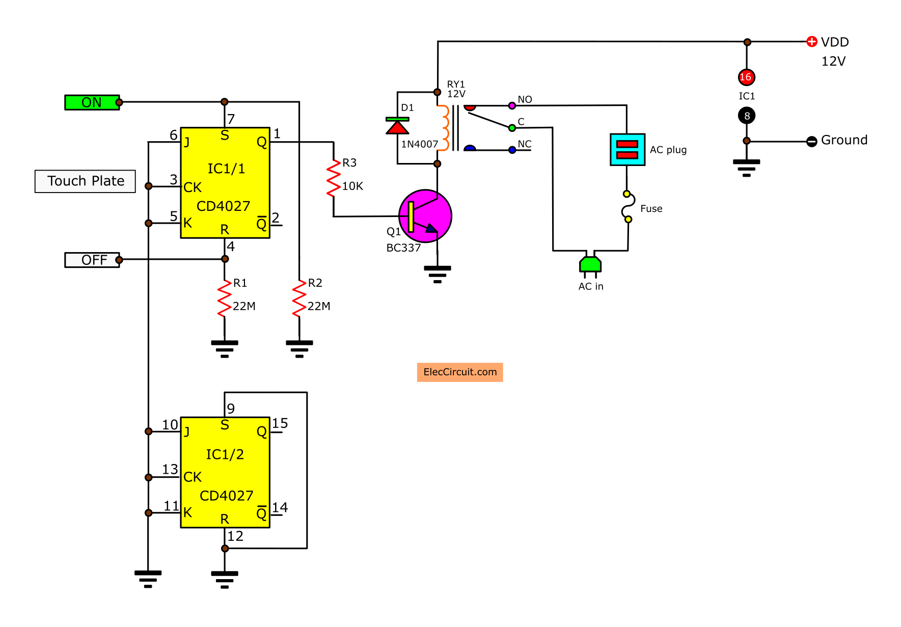
On off switch circuit diagram. Where 0 represents the off condition and 1 represents the on condition. For better understanding i recommend. In this tutorial we are going to make an automatic on off proximity switch using cd 4017. A relay switch is used at the output of the circuit which can be connected with the appliances to make them switch onoff. We uses normal switch in our daily life and after a long time used to these swithing system we can no more interested in that. The circuit diagram for the touch on and off switch circuit is shown in the below image.
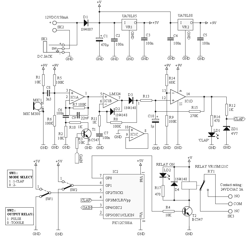
The circuit can be made to change state by applying a signal in this case by pushing a buttonhere i will show you three different ways to. A flip flop or latch is a circuit that has two stable states and can be used to store state information. Remote controlled switch this is the very simple circuit diagram of ir remote control switch. This closes the circuit turning the system on and allowing current to flow unimpeded through the rest of the. So this is the clap switch which will turn on with first clap and turn off with the second clap. Circuit diagram circuit placement.
The circuit has also a good range of upto 20 meters. This is a simple circuit where a n channel enhancement mode mosfet will turn on or off a light. This is the new method to make a 2 way switching connection as it is slightly different from the two wire control method. For good results use a good quality fm transmitter with the circuit. As the name suggests proximity switches are used to sense the presence when some person or object is brought close in proximity and it turns the appliances connected to it on off accordingly. Three push on push off latching circuits.
In this circuit 555 timer ic and 7474 dual positive. How to connect 2 way switch wiring using three wire control. The whole project contains two parts which is an fm transmitter and a rf receiver. If we remove the d type flip flop from the circuit the led will be turned off automatically after some time and this time will be 11xr1xc1 seconds which i have explained in my previous circuit of clap switch. 1 x 33 mω resistor 14 watt 1 x 1 mω resistor 14 watt 1 x bulb with holder regular or cfl 1 x 5v relay module if relay module is not available then you need the following components 1 x 5v. In order to operate a mosfet as a switch it must be operated in cut off and linear or triode region.
1 x 555 timer ic. Share on tumblr remote access to electrical devices are makes us comfortable and if you can control electric device with clap then it makes you very joyful and here we have prototype a simple clap on clap off switch using 555 timer and this circuit can help us to control any electric device here for an example we have taken electric bulb. This method is commonly used now days as it is efficient than the two wire control system. This circuit requires. In the off state a switch looks like an open gap in the circuit. Assume the device is initially off.
We will understand the operation of a mosfet as a switch by considering a simple example circuit.
Gallery of On Off Switch Circuit Diagram