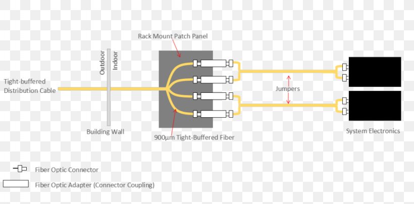
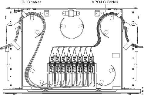
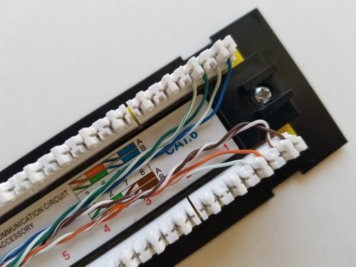
Cables terminated onto rj 45 wall outlets have been terminated onto a patch panel and are connected to a lan switch with. Test the cable from jack to patch panel with the.

Network Panel Box Patch Panel Wiring Diagram Network Rack
Patch panel wiring diagram. Take a piece of utp cable about a foot or so. It reveals the parts of the circuit as simplified shapes and also the power and signal connections in between the devices. Attach the 24 port patch panel and 24 port switch to a rack mounted floor stand in the wiring closet. Patchbays are organized based on the needs of the studio so none of them are laid out the same way. This makes it easy to connect the server to the patch panel with the help of short cables which can as well be moved easily when there is a need to. The patch panel is not marked 568a or 568b.
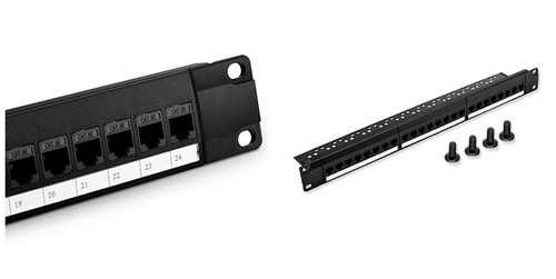
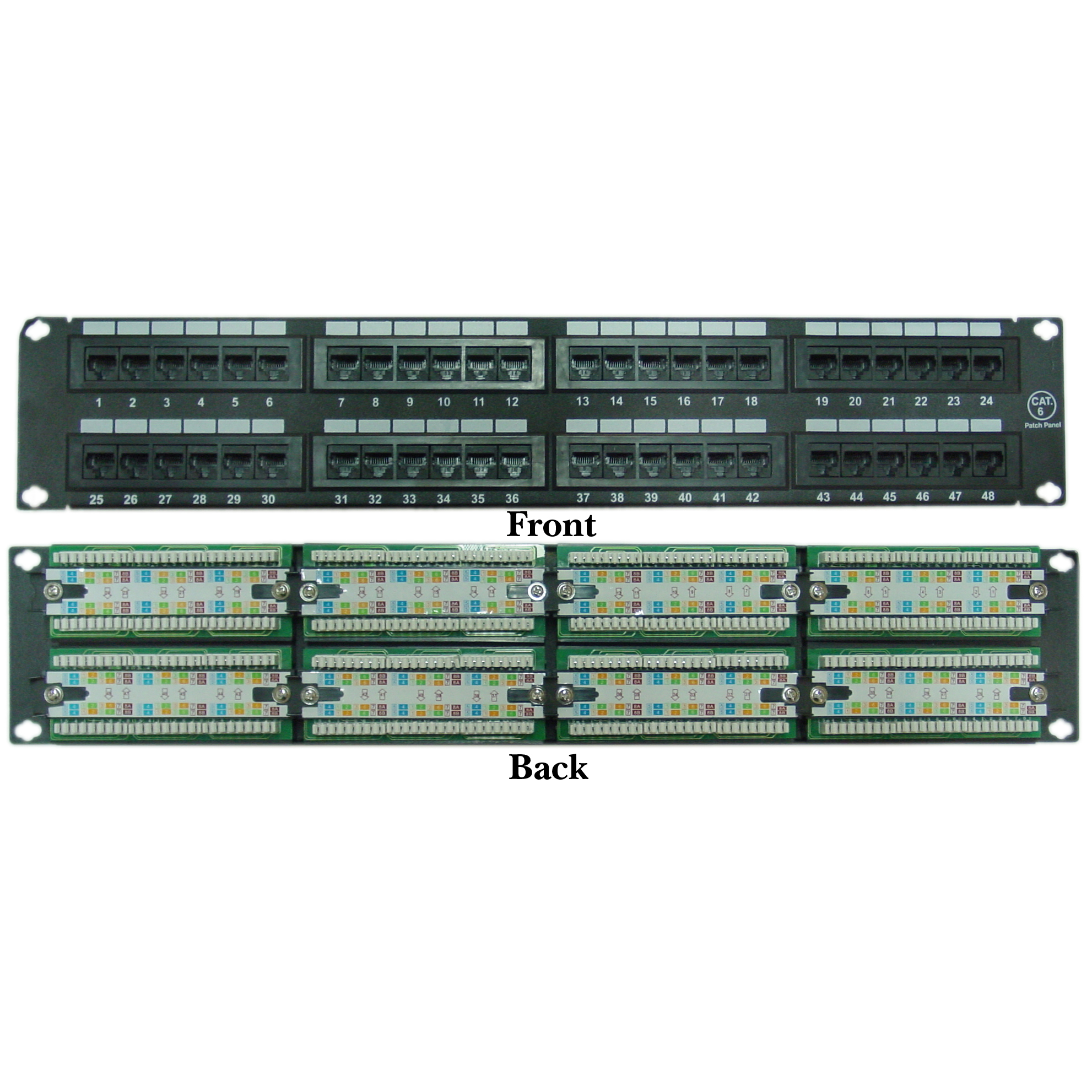
Run the ethernet cables from their jack locations out in the computer room. So when wiring the cat5e patch panel a big issue is the design and quality of the terminations of cat5e patch cables. Buy a patch panel when buying the patch panel ensure it has 110 style insulation displacement connectors. Assortment of leviton cat5e patch panel wiring diagram. How can i tell what it actually is wired for. Monoprice cat6 patch panel punch down tutorial.
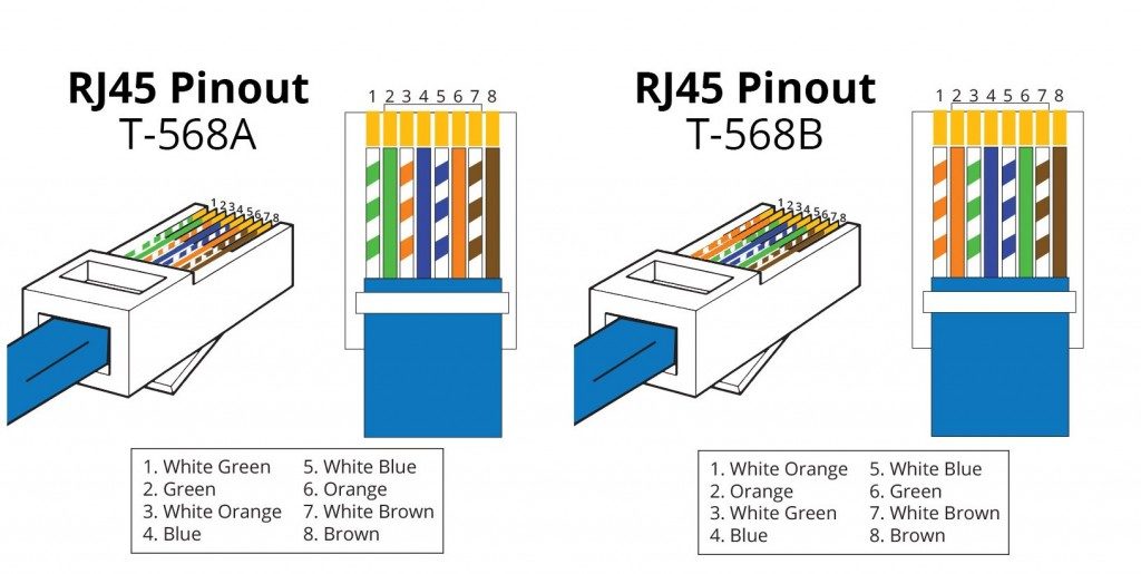
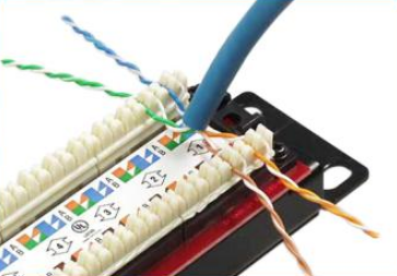
Each cable will come from a wall mounted jack that the installer has placed in the wall. Connect a jack on one end using the 568b wiring scheme. Each part should be set and linked to different parts in particular way. To achieve this kind of wiring consider the following guide on how to wire a patch panel. Patch panel to switch diagram. When choosing a suitable patch cable booted and non booted is two basic types of plug features.
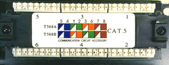
The cat5e patch cable is the basic component to connect end devices to patch panel ports and to connect the ports between two local patch panels. Most patch panels and jacks have diagrams with wire color diagrams for the common t568a and t568b wiring. This is pretty easy. Patch cable tidy ring installation features cable tidy ring example uses cables to bt type wall outlet modules have been terminated onto a patch panel and are connected to a telephone distribution panel with blue patch leads. If not the structure will not work as it should be. A wiring diagram is a streamlined conventional photographic depiction of an electric circuit.
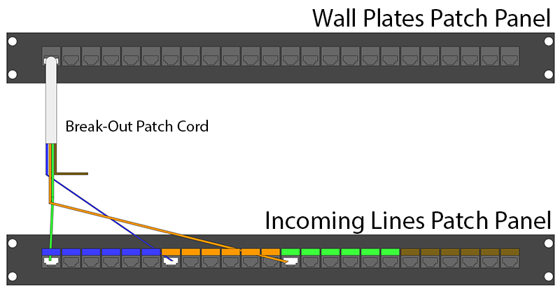
Patch panel wiring diagram cat5e patch panel wiring diagram cat6 patch panel wiring diagram connectix patch panel wiring diagram every electric structure is made up of various diverse pieces. Cables punched down to the back of the patch panel. For instance console channel outputs 1 8 connect to the patch bay using a single cable instead of 8 separate trs cables. This is a huge space saver. Connect the other end to the patch panel in the standard fashion blue orange green brown.

