Programmable logic controller basics video. The following are ten recommended procedures for io wiring.

Plc Aneka Listrik
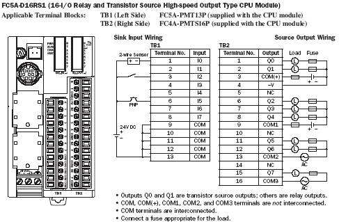
Plc input output wiring diagram. Power supply input dc 24v power supply output wecon plc unit wiring diagram lx1s series plc lx2n3v series plc. Selectable output with analog output of 0 10 vdc. In the picture without common the green points all lead to the same voltage source. This will include a discrete and analog input signal. Verify that all modules are in the correct slots. The device you connect to your analog output is what decides which type of analog signal you should be using.
Remove and lock out input power from the controller and io before any plc installation and wiring begins. The uk1f e7 0a is an 18mm diameter sensor that has a pnp nonc. If your plc is powered by 100 240vac use these two pins to power it upthese two pins are not available on 24vdc plc models. When wiring up the inputs and outputs to the plc the relevant ones must be connected to the input and output terminals with these addresses. This could be a flow controller valve a frequency converter or even an analog input on another plc. Typical output voltages are listed below and roughly ordered by popularity.
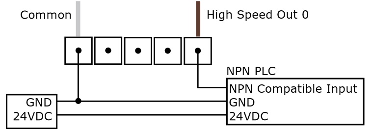
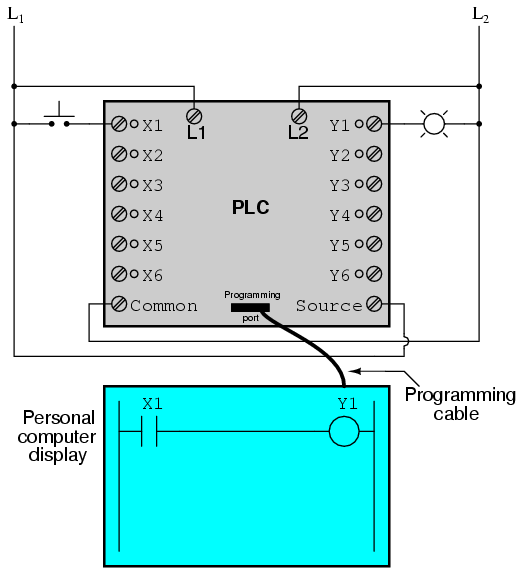
Thus figure 6a indicates that this rung of the ladder program has an input from address x400 and an output to address y430. We will be wiring an ultrasonic sensor into the input of our click plc. The sensing distance is 200mm to 2200mm and has a one hertz switching capacity. Commons take advantage of this frequent situation grouping one side of connections together. Voltage analog output wiring. Source of voltage for input to plc applies source of voltage dc 24 volt.
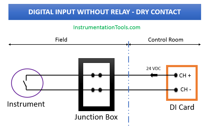
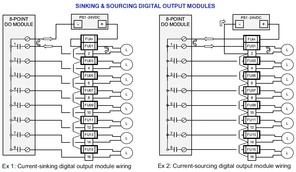
120 vac 24 vdc 12 48 vac. Example of wiring diagram for part of input plc input plc applied is limit switch and proximity swtich while plc applied by plc keyence. In this article we are sharing the basic concepts of plc and dcs control systems wiring diagrams for digital input di digital output do analog input ai and analog output ao signals. Check module type and model number by inspection and on the io wiring diagram. Note that these diagrams are without a barrier or isolator fuses and surge protector for keeping it very simple and understandable. Plc wiring 37 322 output modules as with input modules output modules rarely supply any power but instead act as switches.
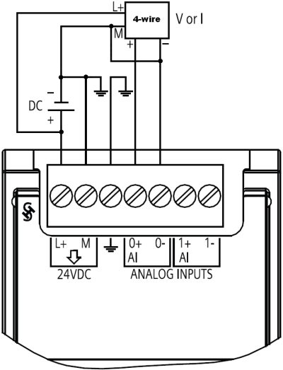
If you want to control a valve with a 4 20 ma signal then your analog output should also be 4 20 ma. Example of wiring diagram plc following way tacking on the cable. Plc wiring diagrams guide include the discrete signals wiring plc digital input modules wiring plc output modules wiring and basics of plc terminations. A legacy model most possibly you are not using this model. External power supplies are connected to the output card and the card will switch the power on or off for each output. The picture to the right shows an example of what the wiring of a plc with 4 inputs would look like.



.png)
.jpg)
