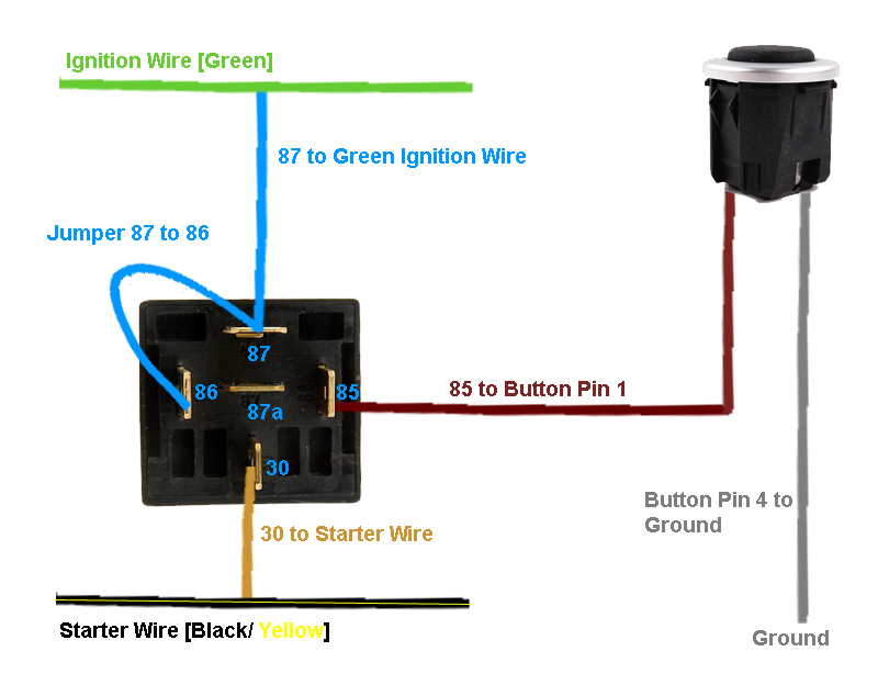
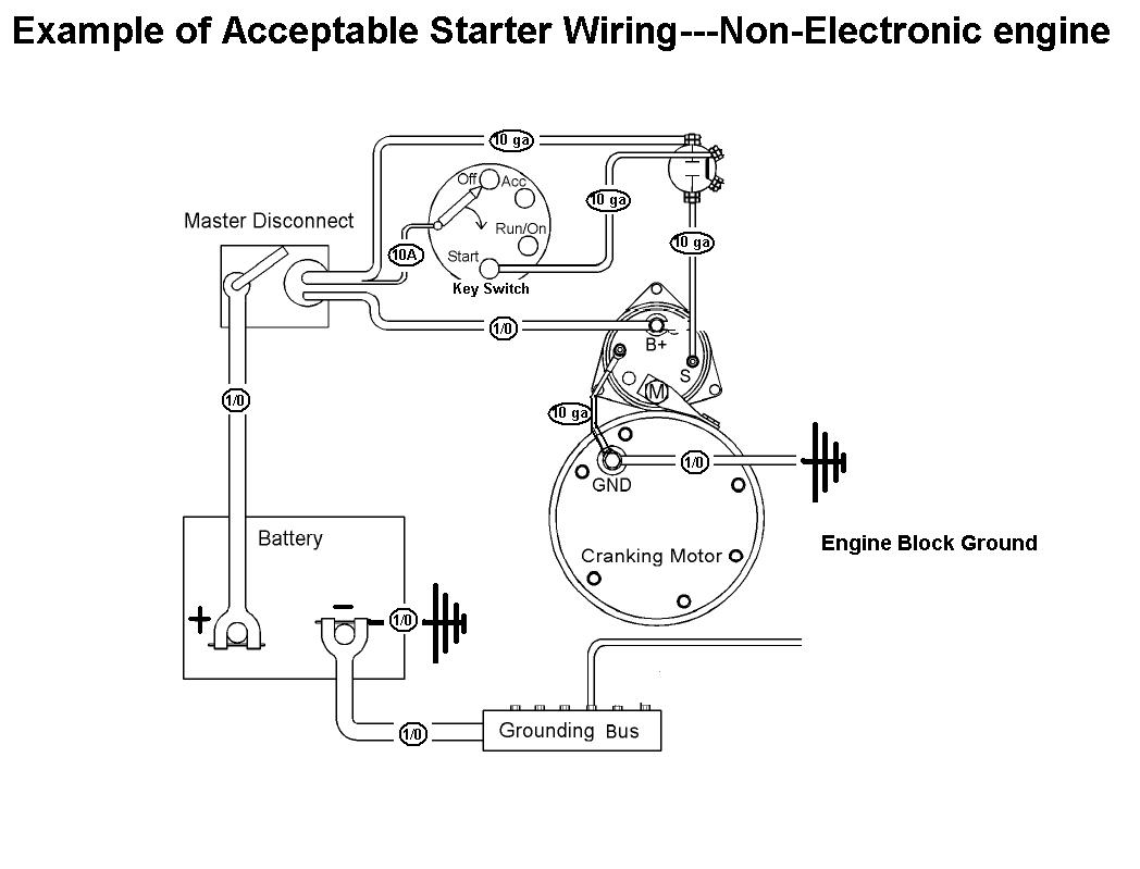
One relay for control and the motor. Larbi 12v 20a horn button push starter switch weatherproof rubber cover and 2 terminals for car boat track switch sealed push button horn engine start switch.
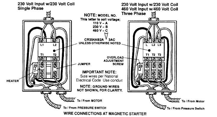
Installing The Magnetic Starter
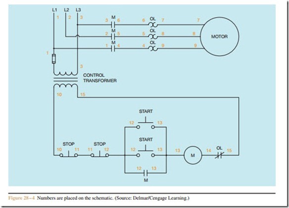
Push button motor starter wiring diagram. Wiring diagram contains numerous comprehensive illustrations that show the relationship of varied items. Basic wiring for motor contol circuitry of a starter two wire control two wire control circuits or low voltage release one of the common control wiring circuits used is known as two wire or low voltage release lvr. Voltage drop test a starter motor circuit duration. It contains instructions and diagrams for various kinds of wiring techniques and other things like lights home windows and so forth. Bypassing the push button starter on an atv. Free shipping on your first order shipped by amazon.
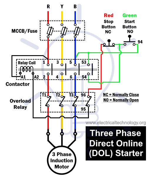
All connection i shown with complete guide. When you press the start button and the stop button. Push button starter switch wiring diagram push button ignition switch wiring diagram push button start switch wiring diagram push button starter switch wiring diagram every electrical arrangement consists of various distinct parts. Otherwise the arrangement wont work as it ought to be. Emolatur is offline push button for stop. Push button circuit wiring diagram 0 0 4 reference point identified on starter corresponds with number shown in push button station wiring diagram.
48 out of 5 stars 55. It uses three contactors an overload relay one auxiliary contact block a normally open start pushbutton a normally closed stop pushbutton an on delay timer of 0 20 seconds and a power supply with a fuse. In the above one phase motor wiring i first connect a 2 pole circuit breaker and after that i connect the supply to motor starter and then i do cont actor coil wiring with normally close push button switch and normally open push button switch and in last i do connection between capacitor. Push button starter switch wiring diagram circuit using 11n push button starter switch wiring diagram. Get it as soon as thu jul 23. The above diagram is a complete method of single phase motor wiring with circuit breaker and contactor.
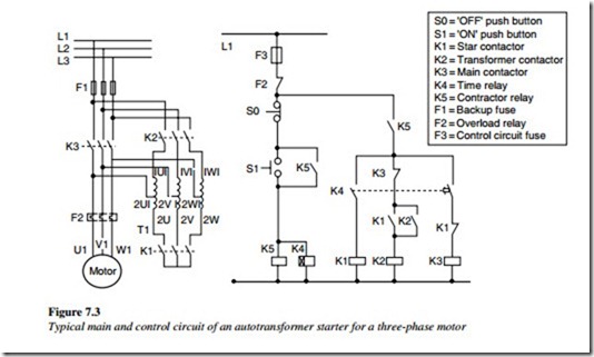
Each component ought to be placed and linked to other parts in specific manner. It utilizes a main tained contact type of pilot device such as a thermostat float switch or presence sensor. See image below for an example of 3 wire control being used to pull in a contactor to start a 3 phase motor. In the above three phase dol starter wiring diagram. The following diagram is shown for 3 phase motor control of a delta star connection. Start stop control wiring diagrams.
Wye delta open transition 3 phase motors. Power line symbolized by weighted lines. 0 junction of conductors absence of node indicates wires cross with no connection. In the below dol starter wiring diagram i shown a molded case circuit breaker a magnetic contactor normally open push button normally close push button switch thermal overload relay motor trip indicator and 3 phase motor. Single station with the starter. Simple wiring for toggle switch and push button start.


