Each component ought to be placed and linked to other parts in specific manner. For more circuit examples see the fritzing project page.

Push Button Switch That Turn On A Motor In One Push And Turn
Push button switch circuit diagram. An scr is a gate controlled switch which needs a triggering pulse. Otherwise the arrangement wont work as it ought to be. The circuit that we are making is ideal to use as a push button switch. L the schematic or line diagram includes all the components of the control circuit and indicates their. Momentary button or switch 10k ohm resistor hook up wires breadboard circuit. Usually these switches can be made by using a binary divider or 555 timer ic but they consume current even in off state and it makes the process a bit complicated.
A push button can also be used for the triggering purpose like of scr. When connecting in between of supply and the circuit we should only connect the wires with both the legs of the push button as shown in the circuit below. It will allow switching loads on and off through a push button. Typical wiring diagrams for push button control stations 3 genera information at each circuit is illustrated with a control circuit continued schematic or line diagram and a control station wiring diagram. The first two red and black connect to the two long vertical rows on the side of the breadboard to provide access to the 5 volt supply and ground. Here relay is 24 v dc operated.
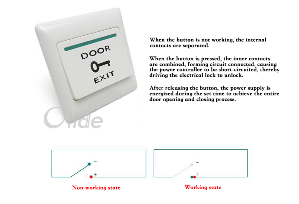
Push button starter switch wiring diagram push button ignition switch wiring diagram push button start switch wiring diagram push button starter switch wiring diagram every electrical arrangement consists of various distinct parts. Image developed using fritzing. It allows the current to flow through it only when we press or switch on the button the led will start glowing when it is pressed the first time. A flip flop or latch is a circuit that has two stable states and can be used to store state information. Typical push buttons are momentary meaning they are designed with a spring to keep the button contacts open or closed at all times. How to use a push button.
Push buttons shown in figure 1 are the most common type of control devices found in industrial facilities. Three push on push off latching circuits. Connect three wires to the board. Almost all industrial machines contain push buttons even if the facilities operation is to set to run automatically. Working of push onoff button led circuit. Step 2 when supply comes to relay coil relay should be on.
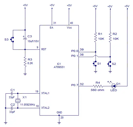
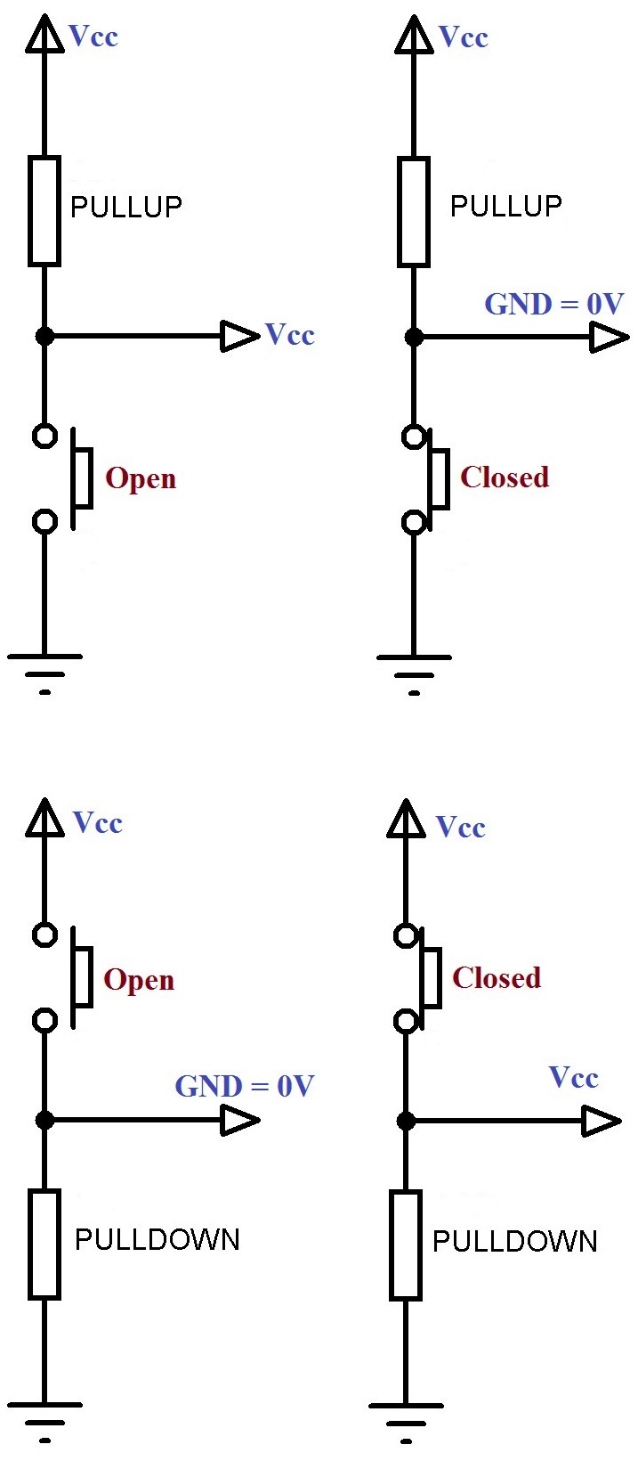
The common leg of onoff push button is connected to 5v supply and the other one is connected to the led via resistor as shown in circuit diagram. Initially push button does not allow the current to flow through it but when it is pressed it completes the circuit and led will start to glow. We will go with step by step. These two step we see in following picture. Step 1 when we press push button relay should be on it means we use normally open type push button because when we press this switch supply goes forward. The one leg of push button is connected to 5v supply and the other one is connected with led via the resistor as shown in circuit diagram.
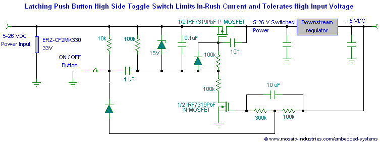
The circuit can be made to change state by applying a signal in this case by pushing a buttonhere i will show you three different ways to.
Gallery of Push Button Switch Circuit Diagram