Time delay relay can provide a short delay after power is turned on and before switching on the device. The working is very simple and is explained below.

Relay Toggle Switch Eeweb Community
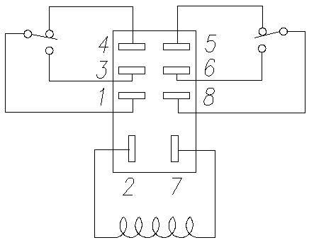
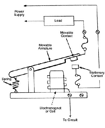
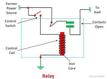
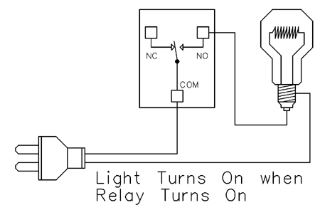
Relay switch circuit diagram. Electronic relay switch circuit diagram and its working. Switch connections of relay are mostly named as pole com normally closenc normally open nopole and com is equal to common normally closed and normally open is always connected with the moving part of the switch. There you have it. Triac is used at the place of coil relay to switch on and off. Solid state relay is a type of switch to activate load by using without any mechanical parts. Now in the diagram below i have added a motor starter.
Now these diagrams are known as relay logic or ladder diagrams. Relay switch circuit diagram working of the basic 5v relay circuit. There are a variety of electrical and electronic devices which are classified as output devices such devices are used to control or operate some external physical process of a machine or device. These output devices are commonly called actuators. At the initial condition when switch is open no current flow through coil hence common port of relay is connected to no normally open pin so the. In this relay switch circuit the relay load has been connected to the pnp transistors collector.
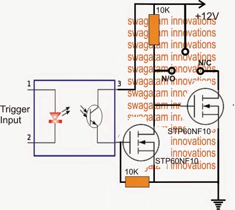
In this there is only semiconductor devices used no mechanical coil relay is used to switching the connected load. An onoff switch is added for the switching purpose of the relay. The circuit is based on the rc time delay and zener controlled switch. When the power to the circuit is turned on the 1000µf capacitor charges through the 100kω variable resistor. It reveals the components of the circuit as simplified shapes and also the power and signal connections in between the tools. In the above circuit 5v relay is powered by a 9v battery.
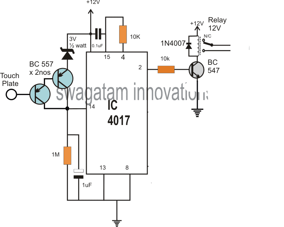
The circuit can be operated with 12 volt dc but you can also operate it with 5 6 or 9 volts make sure to use the relay according to the voltage. It will continue downward as you will see later on. The operation of this circuit is the same as the previous relay switching circuit. The on off switching action of the transistor and coil occurs when vin is low transistor on and when vin is high transistor off. Its using relays to control the circuit and also the diagram will begin to take the shape of a ladder as the relay logic grows. If you want to design a switch circuit to turn on and turn off without reach a physical switch then try this simple clap switch circuit with relay this circuit is designed with timer ic 555 dual d flip flop ic 7474 and a electromagnetic relay.
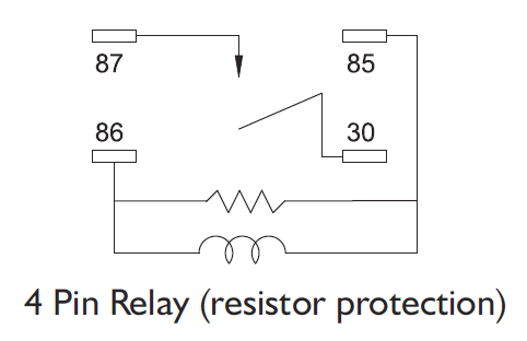
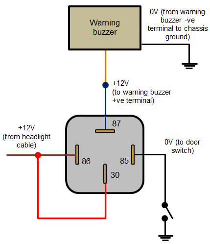
Mentioned in the topic how to use relay example of basic schematic of relay circuit diagram. A wiring diagram is a simplified traditional pictorial depiction of an electrical circuit. Solid state relay optocoupler relay. Assortment of 12 volt relay wiring diagram. The circuit requires a small audio signal to switch on the relay such as equal to the audio output of a headphone jack of any equipment.
