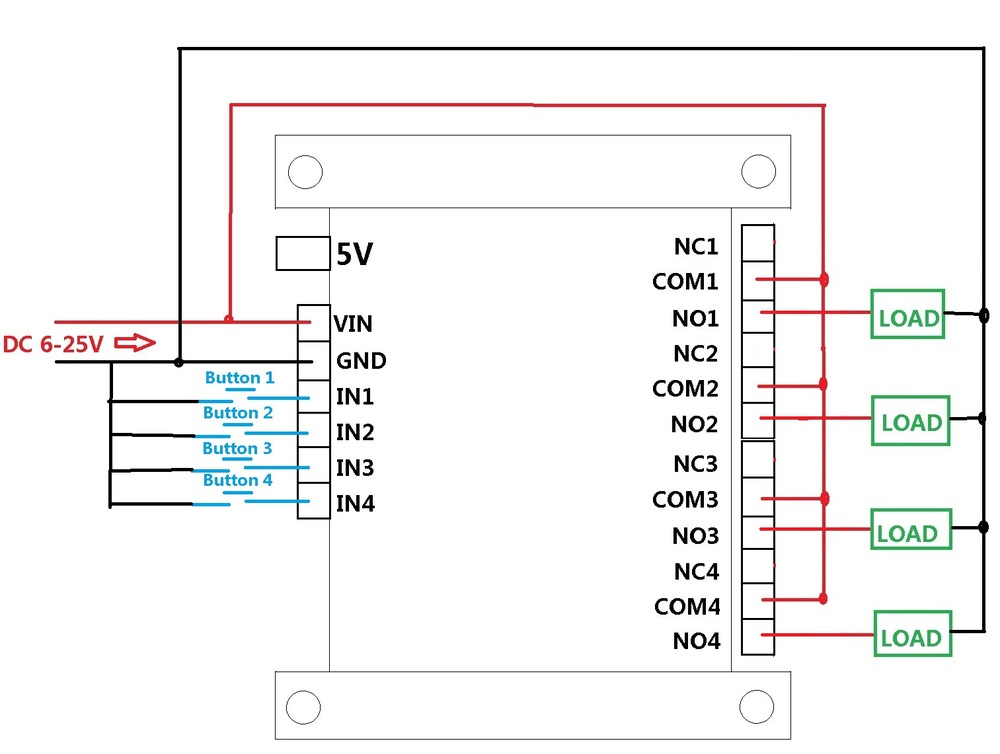
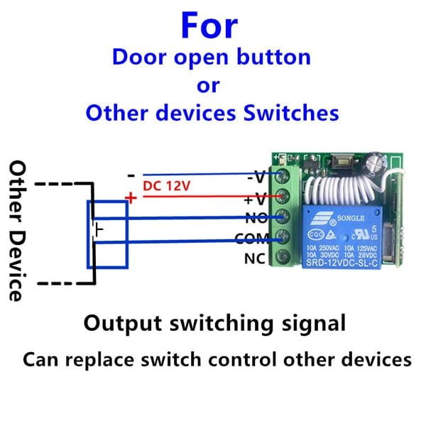
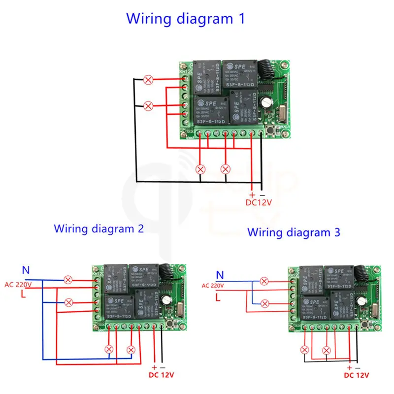
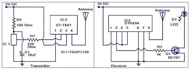
For good results use a good quality fm transmitter with the circuit. Receiver circuit is connected to ac appliance via relay so that we can control the light remotely.
433mhz Remote Control
Rf remote control switch circuit diagram. We uses normal switch in our daily life and after a long time used to these swithing system we can no more interested in that. Share on tumblr rf remote control circuit designed with 434 mhz ask amplitude shift keying transmitter and receiver here ic ht12e act as encoder and ic ht12d act as decoder this circuit is constructed with easy available components. The whole project contains two parts which is an fm transmitter and a rf receiver. A relay switch is used at the output of the circuit which can be connected with the appliances to make them switch onoff. This is a good solution for a unique and so interesting idea to wireless switching system to control the home appliance. We have used ic 4017 to convert it into a push on push off switch.
This is a project of an rf remote control relay switch circuit. This remote gives approximately 150 meter coverage by extending the ariel wire it can be increased up to 200 meters. In this remote controlled switch circuit we are using tv remote to onoff the ac light by pressing any button of remote and using the tsop1738 at receiver end. This is the very simple circuit diagram of ir remote control switch. The circuit has also a good range of upto 20 meters. The wireless rf remote control onoff switch is used as a switch of your fan lights or other electronic apparatuses even if you are in another room.
The circuit is using a dpdt relay at the output from which you can connect your home appliances to operate them wirelessly like fan lamp etc. The coil l1 in the receiver circuit is a hand made air cored coil having 6 turns of 24 enameled wire coiled intently on a 5mm structure.
Gallery of Rf Remote Control Switch Circuit Diagram


